Storage system and storage system data migration method

a storage system and data migration technology, applied in the field of storage system and storage system data migration methods, can solve the problems of increasing the operational cost of the storage apparatus, reducing the cost-effectiveness of the disk, and not being able to achieve the results that correspond to the initial data migration plan, so as to improve the ease of use of users

Inactive Publication Date: 2012-05-31
HITACHI LTD
View PDF2 Cites 14 Cited by
  • Summary
  • Abstract
  • Description
  • Claims
  • Application Information

AI Technical Summary

Benefits of technology

[0011]With the foregoing in mind, an object of the present invention is to provide a storage system and storage system data migration method that can enhance the ease-of-use of a user when migrating data to a plurality of volumes as a group. Another object of the present invention is to provide a storage system and storage system data migration method that can automatically modify an initial migration plan in accordance with the state of a migration destination when migrating data to a plurality of volumes as a group. Yet other objects of the present invention should become clear from the disclosure of the embodiments, which will be explained hereinbelow.

Problems solved by technology

When an expensive disk is used as the storage destination for data to be stored over a long period of time, as described hereinabove, the cost-effectiveness of the disk decreases, and the operational cost of the storage apparatus rises.
However, since the state of a storage apparatus changes in various ways, there is no guarantee of achieving results that correspond to the initial data migration plan.
If a failure of some sort should occur in the migration-destination storage apparatus during data migration, for example, even if data migration processing is capable of continuing at the time the failure occurs, there will be occasions when the results anticipated by the initial data migration plan will not be achievable thereafter due to the secondary effects of the failure.
For example, despite the fact that data migration was executed for the purpose of improving response performance, if the load on the data migration-destination storage apparatus rises, there are times when the anticipated response performance cannot be achieved following completion of the data migration.
In this case, a user must go to the added trouble of devising a new data migration plan for realizing the initially anticipated response performance, and re-migrating the data.
Further, it is also possible that data migration processing will fail part way through due to the failure that occurred in the migration-destination storage apparatus.
Therefore, carrying out repeated data migrations to the same migration-targeted volume reduces customer satisfaction.
Thus, in the prior art, data migration that takes into consideration the fluctuating state of a storage apparatus is not examined, and as such, is not very user-friendly.

Method used


Image

  • Storage system and storage system data migration method
  • Storage system and storage system data migration method
  • Storage system and storage system data migration method

Examples


first embodiment

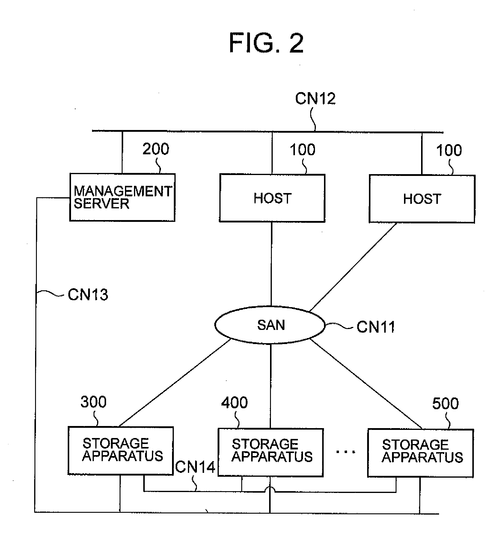
[0075]FIG. 2 is a schematic diagram showing the entire constitution of a storage system. This storage system, for example, is constituted comprising one or a plurality of hosts 100, at least one management server 200, and a plurality of storage apparatuses 300, 400, 500.

[0076]A host 100, for example, is constituted as a server computer or a mainframe computer, and reads and writes data using volumes provided by the storage apparatuses 300, 400, 500.

[0077]The management server 200 is a computer, which corresponds to the “management apparatus”, and collects information from the respective storage apparatuses 300, 400, 500, and hosts 100, and manages the migration of data inside the storage system. This will be explained in detail hereinbelow.

[0078]The network composition will be explained. The hosts 100, for example, are respectively connected to the storage apparatuses 300, 400, 500 via a network CN11 used for data input and output, such as a LAN (Local Area Network) or a SAN (Storag...

second embodiment

[0191]A second embodiment of the present invention will be explained based on FIGS. 22 and 23. In this embodiment, a group of migration-source volumes, which are distributed and arranged in a plurality of storage apparatuses, is migrated all at once to a plurality of migration-destination storage apparatuses. Since each of the following embodiments, to include this embodiment, correspond to variations of the above-mentioned first embodiment, redundant explanations will be omitted, and the focus will be on explaining the points of difference with the first embodiment.

[0192]FIG. 22 is a schematic diagram showing the overall constitution of a storage system according to this embodiment. This storage system has a plurality of hosts 100 (only one is shown in the figure), a management server 200A, and a plurality of storage apparatuses 300, 400, 500, 600, 700. Furthermore, this embodiment can also comprise other storage apparatuses besides the storages apparatuses 300, 400, 500, 600, 700 ...

third embodiment

[0205]A third embodiment of the present invention will be explained based on FIGS. 24 through 26. In this embodiment, forming a local copy 442A of a volume inside the migration-source storage apparatus 400 will appear to a host 100 as if data migration has been completed.

[0206]This embodiment comprises a plurality of hosts 100 (only one is shown in the figure), a management server 200B, and a plurality of storage apparatuses 300, 400, 500, 600, 700 the same as the above-mentioned second embodiment. Also similar to the above-mentioned second embodiment, a parent resource group 800B comprising a plurality of resource groups 801B is the target of data migration. The resource group 801B inside storage apparatus 300, and the resource group 801B inside storage apparatus 400 form a remote copy pair. Explanations in common with those of the second embodiment will be omitted so as to focus on the points of difference.

[0207]The management server 200B of this embodiment differs from that of th...


PUM


Abstract

This storage system modifies the migration plan in accordance with the state of the migration destination when a plurality of volumes are migrated all at once. Migration-source volumes are migrated collectively to volumes inside the migration-destination storage apparatus. The user can make settings related to migration-source volumes and migration-destination volumes in a migration plan, and can establish a mid-process control plan for modifying the migration plan in the middle of processing. If a failure occurs in the migration-destination storage apparatus subsequent to the commencement of data migration processing, a processing method controller either cancels or temporarily halts the data migration processing, or changes the migration destination, on the basis of the mid-process control plan. When changing the migration destination, a previously selected alternate storage apparatus is selected as the new migration-destination storage apparatus. When a failure occurs in the alternate storage apparatus, yet another alternate storage apparatus is selected.

Description

CROSS-REFERENCE TO RELATED APPLICATIONS[0001]The present application is a continuation of U.S. application Ser. No. 13 / 167,867, filed Jun. 24, 2011; which is a continuation of U.S. application Ser. No. 12 / 873,432, filed Sep. 1, 2010, now U.S. Pat. No. 7,996,640; which is a continuation of U.S. application Ser. No. 12 / 269,164, filed Nov. 12, 2008, now U.S. Pat. No. 7,805,585; which is a continuation of U.S. application Ser. No. 11 / 445,202, filed Jun. 2, 2006, now U.S. Pat. No. 7,469,325; which relates to and claims priority from Japanese Patent Application No. 2006-110494 filed on Apr. 13, 2006, the entire disclosures of which are incorporated herein by reference.BACKGROUND OF THE INVENTION[0002]The present invention relates to a storage system and a storage system data migration method.[0003]In recent years, the disk capacity of a storage apparatus, which provides a data storage region, has been increased in line with the larger amounts of data being processed by a host computer (he...

Claims


Application Information

Patent Timeline
Patent Type & Authority Applications(United States)
IPC IPC(8): G06F12/02
CPCG06F3/0605G06F3/0647H04L67/1097G06F11/3409G06F11/3433G06F3/067
Inventor SHIBAYAMA, TSUKASAOKADA, WATARUSAKASHITA, YUKINORIHIRAIWA, YURISATO, MASAHIDE
Owner HITACHI LTD
Why Eureka
Try Eureka