Muzzle-loading rifle equipped with a gunpowder-proof sealed breech plug

Active Publication Date: 2012-06-07
DIKAR S COOP
View PDF4 Cites 3 Cited by
  • Summary
  • Abstract
  • Description
  • Claims
  • Application Information

AI Technical Summary

Benefits of technology

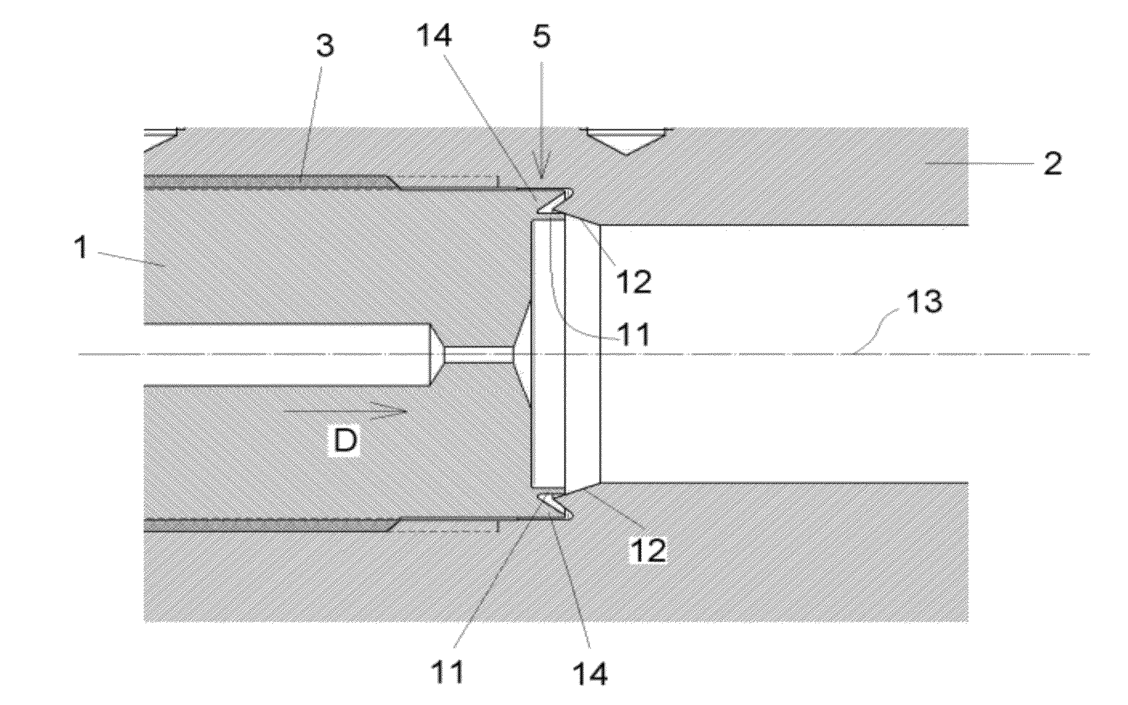
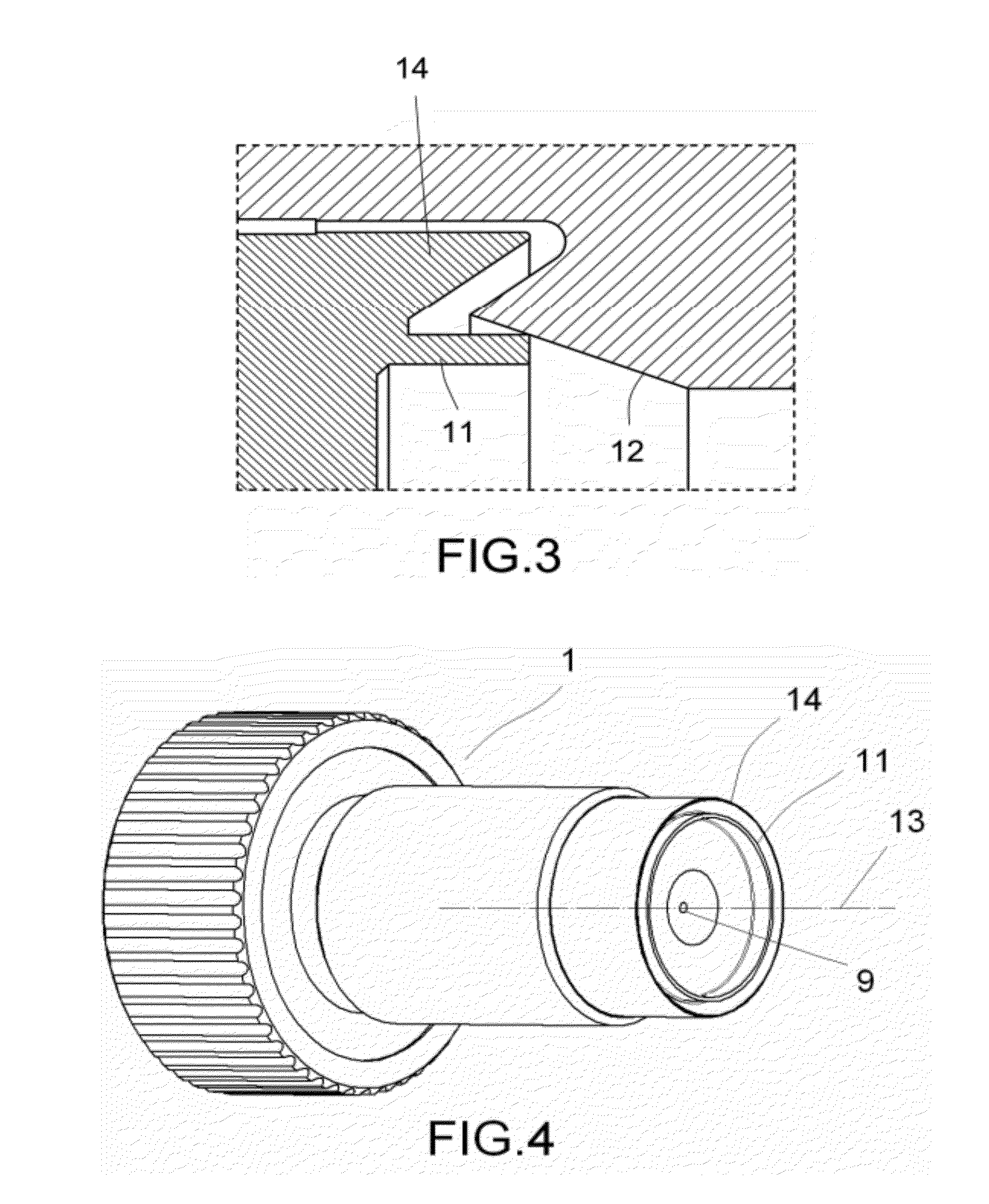
[0007]In order to achieve the aforementioned objectives the invention proposes a muzzle-loading rifle provided with a breech plug and a barrel, both of them fixed to each other in a connection area, wherein the breech plug comprises a first end further away from the part of the barrel where a bullet is to be housed and a second end closer to said part of the barrel. According to the invention, the second end of the breech plug is provided with a flange that presses internally against a seating surface of the barrel when the breech plug is fitted in the interior of the barrel. Said pressure increases when the gunpowder located near the second end of the breech plug explodes. In other words, the flange expands against the seating surface when the gunpowder explodes, increasing the pressure it exerts on the seating surface and therefore improving the sealing effect.
[0008]The flange of the breech plug is continuous, i.e. it does not have any breaks or gaps. Contact between the flange and the seating surface occurs in the area of 360° around the longitudinal axis of the breech plug. This is possible because the flange bends against the seating surface and may thus form a c

Problems solved by technology

These traces of gunpowder make it very difficult to detach the breech plug from the barrel, so much that in some cases it is impossible to detach the breech plug with the traditional tools the user carries with them.
In more extreme cases it is impossible to remove the breech plug without damaging it, even when securing the rifle on work benches and using large levering tools.
Bearing in mind that the breech plug must be detached from the barrel every day (so that it may be cleaned carefully in order to remove the traces of gunpowder and other impurities that may block the internal conduit), the difficulty or impossibility of separating both members can cause great inconvenience for the user.
These solutions may work for low-pressure explosio

Method used


Image

  • Muzzle-loading rifle equipped with a gunpowder-proof sealed breech plug
  • Muzzle-loading rifle equipped with a gunpowder-proof sealed breech plug
  • Muzzle-loading rifle equipped with a gunpowder-proof sealed breech plug

Examples


Embodiment Construction

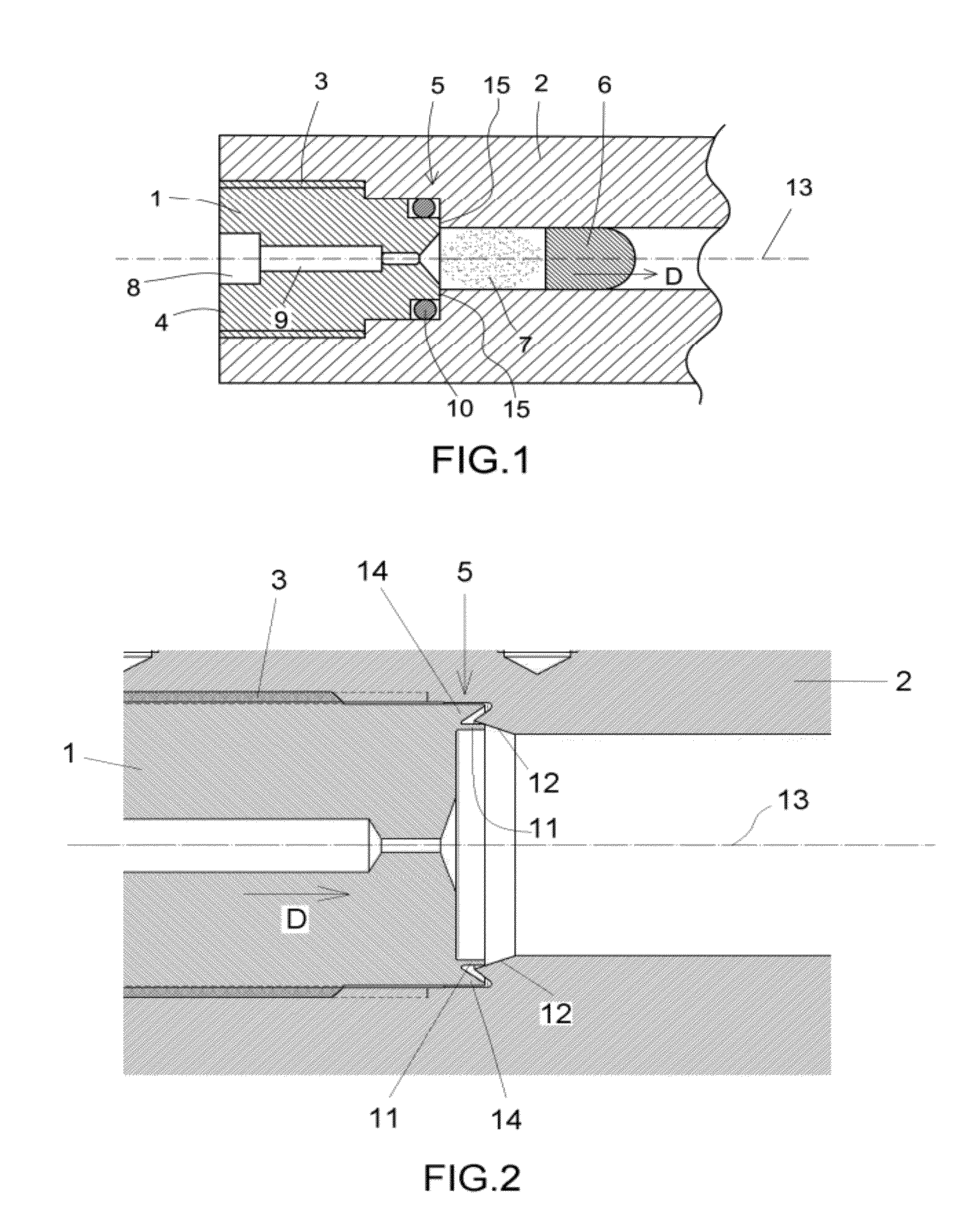
[0016]FIG. 1 shows a cross-section of a conventional muzzle-loading rifle, in particular the area of the rifle in which the breech plug (1) is located inside the barrel (2). In the rifle shown in the figure the breech plug (1) is fixed to the barrel (2) by means of a threaded connection area (3). The breech plug (1) comprises a first end (4) and a second end (5). A bullet (6) is also shown housed inside the barrel (2) in front of a certain amount of gunpowder (7). As seen, the first end (4) is the end of the breech plug (1) further from the bullet (6), whereas the second end (5) is the end closer to the bullet (6).

[0017]In the rifle shown in the figure the shot occurs as follows. Firstly, an ignition occurs in the chamber (8) in the first end (4) of the breech plug (1). Said ignition travels along an internal conduit (9) of the breech plug (1) until it reaches the second end (5) of the breech plug (1). When the ignition reaches the gunpowder (7) an explosion occurs, causing the bull...


PUM


Abstract

Muzzle-loading rifle, which comprises a breech plug (1) and a barrel (2), both fixed in a connection area (3), characterised in that the breech plug (1) is provided with a continuous flange (11) that presses from inside against a seating surface (12) of the barrel (2) when the breech plug (1) is fitted in the interior of the barrel (2), so that said pressure increases when the powder (7) explodes on the second end (5) of the breech plug (1). As a result, the seal between the breech plug (1) and the barrel (2) is strengthened and the gunpowder is prevented from reaching the connection area (3), thereby making it easier to detach the breech plug (1).

Description

TECHNICAL FIELD[0001]The invention relates to a muzzle-loading rifle (also known as muzzleloader), i.e. a rifle in which the gunpowder and bullet are loaded and pressed into the barrel manually. More particularly, the invention has to do with the breech plug and the barrel of said rifle.PRIOR ART[0002]A muzzle-loading rifle is a rifle that, in structural and functional terms, replicates old-fashioned, traditional rifles and gives the user the feeling that they are firing an antique weapon in accordance with classical hunting techniques. Specifically, a muzzle-loading rifle is mainly characterised in that the gunpowder and the bullet must be manually inserted into the bottom of the barrel and pressed down before the shot can be fired.[0003]After the gunpowder and the bullet have been pressed into the bottom of the barrel (next to the breech plug), the trigger is pulled, the shot happening as follows: the pulling of the trigger causes an ignition at the end of the breech plug opposite...

Claims


Application Information

Patent Timeline
IPC IPC(8): F41C9/08F41A21/00
CPCF41A3/30F41C9/08F41A3/74
Inventor LIZARRALDE IBARGUREN, INIGO
Owner DIKAR S COOP
Why Eureka
Try Eureka