Fuel container for motor vehicles with a tie rod

a technology of fuel containers and motor vehicles, applied in the field of fuel containers, can solve the problems of ineffectiveness, difficulty in imagining, and how to achieve the

Active Publication Date: 2012-06-07
MAGNA STEYR FUEL SYST
View PDF15 Cites 48 Cited by
  • Summary
  • Abstract
  • Description
  • Claims
  • Application Information

AI Technical Summary

Benefits of technology

[0006]An object of the invention is, therefore, to equip a two-shelled fuel container with a reinforcement which is effective under internal pressure, can be positioned precisely and, after co

Problems solved by technology

Because the spacers are not stops which are welded together, they cannot transfer any tensile forces, and therefore are not effective when overpressure prevails in the tank
It is not disclos

Method used


Image

  • Fuel container for motor vehicles with a tie rod
  • Fuel container for motor vehicles with a tie rod
  • Fuel container for motor vehicles with a tie rod

Examples


Embodiment Construction

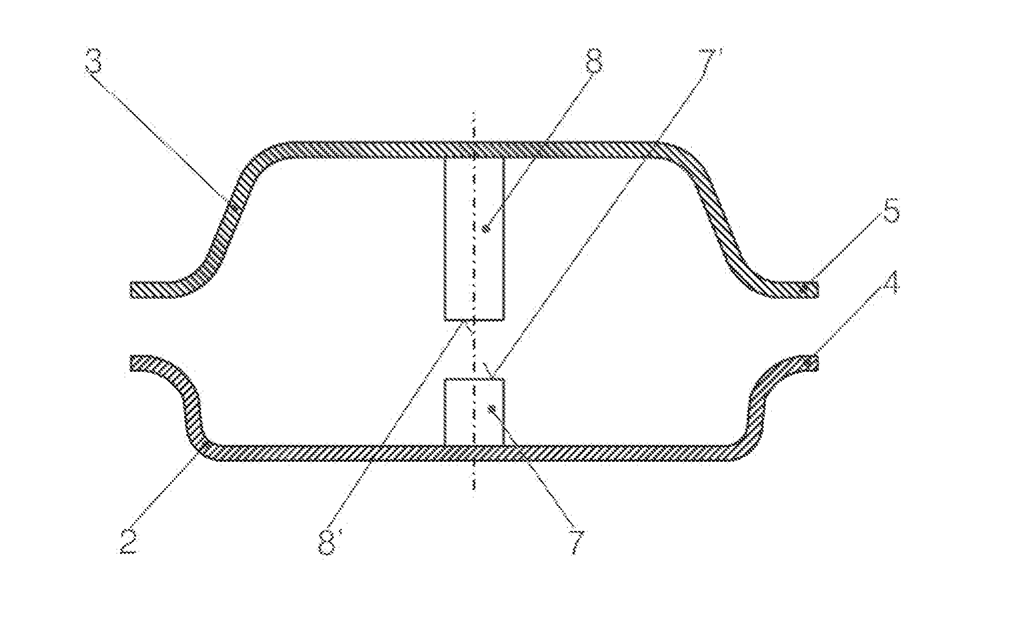
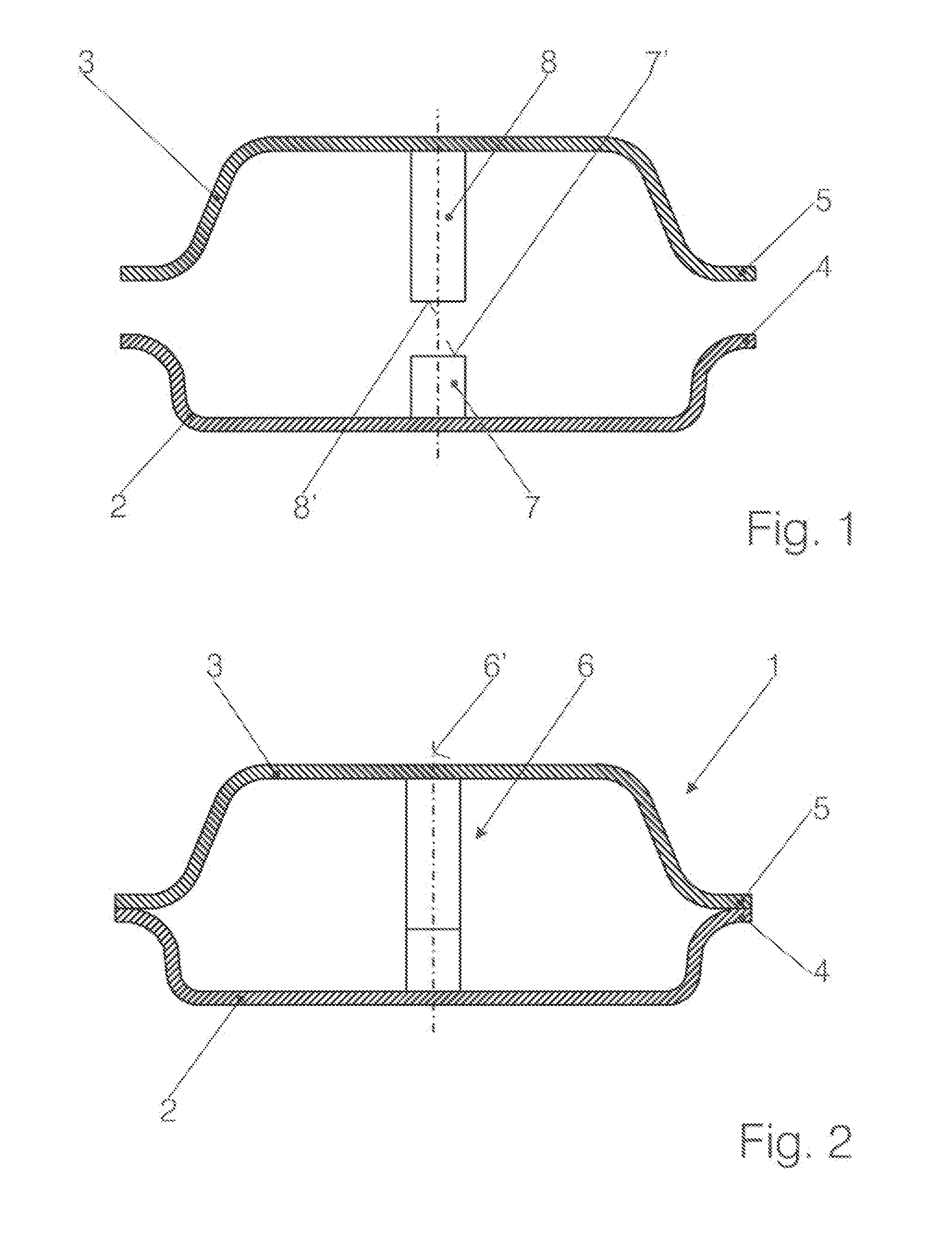
[0024]As illustrated in FIGS. 1 and 2, a fuel container 1 is formed of a first shell 2 and a second shell 3. Each shell has a peripheral flange 4 and 5 respectively configured to permit connection of the shells 2, 3, for example, by a weld technique. In FIG. 1, the shells are illustrated before their connection, and in FIG. 2 they are shown after their connection. A column 6 having a longitudinal axis 6′ is provided in the volume of the container 1 thus formed for reinforcement (a plurality of columns may also be provided). The purpose of the column is to prevent a bulging of the shells 2, 3 as a result of internal pressure within the volume defined by the connection of the shells 2, 3.

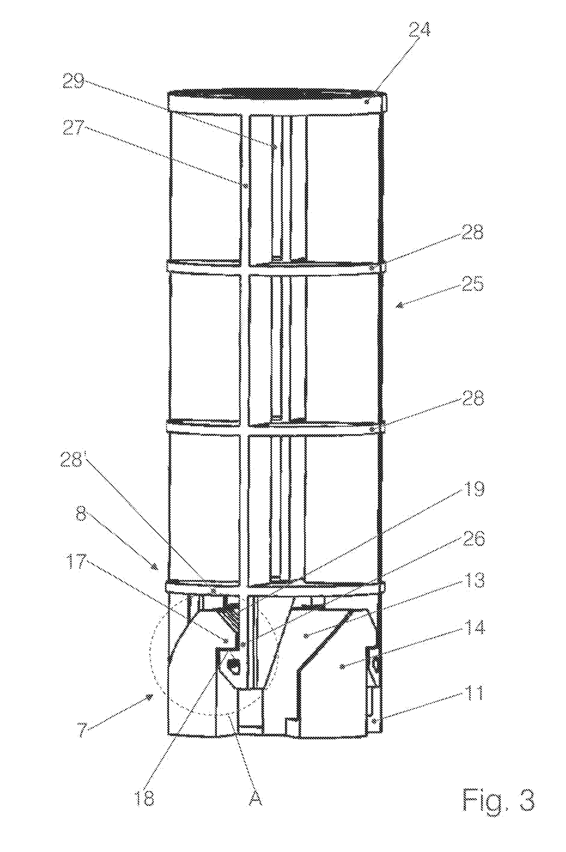
[0025]The column 6 includes a first column part 7 and a second column part 8 which, before the shells 2, 3 are joined, are connected together, via for example, a weld technique, to their respective shell provided they are not formed in one piece therewith. The end 7′ of the firs column part 7 and the ...


PUM


Abstract

A fuel container operating under overpressure and consisting of two shells is to be reinforced by means of an inner column so that, when the two shells are conjoined, a tension resistant connection is created. For this purpose, the column consists of a first and a second part connected to the respective shell, one part having catches, the other part having latching hooks, which catches and latching hooks for a tension resistant snap-in connection when joined together. For this purpose, both parts have latching surfaces and deflecting surfaces and the latching hook is resiliently displaceable.

Description

CROSS-REFERENCE TO RELATED APPLICATIONS[0001]The present application is a National Stage Application of PCT International Application No. PCT / EP2010 / 061437 (filed on Aug. 5, 2010), under 35 U.S.C.§371, which claims priority to German Patent Application No 10 2009 036 911.2 (filed on Aug. 11, 2009), which are each hereby incorporated by reference in their respective entireties.FIELD OF THE INVENTION[0002]The invention relates to a fuel container which is subjected to overpressure, at least temporarily, and is formed of two shells which are interconnected around their periphery and inside the periphery by way of at least one column.[0003]For operational reasons, it is appropriate to design fuel containers for a higher pressure level of up to 500 mBar. The increased internal pressure exerts considerable forces onto the inner face of the large-area shells, which leads to an outward curvature thereof. Such a distended container would exceed the predefined installation dimensions.BACKGROU...

Claims


Application Information

Patent Timeline
IPC IPC(8): B65D6/00
CPCB60K2015/03467B60K15/03177
Inventor VARGA, LASZLO
Owner MAGNA STEYR FUEL SYST
Why Eureka
Try Eureka