End plate, and rotor for rotary electric machine which employs the end plate

a technology of end plates and rotors, which is applied in the direction of dynamo-electric machines, magnetic circuit rotating parts, and shape/form/construction of magnetic circuits, etc., can solve the problems of increasing the number of magnet portions, high cost and relatively low rigidity of non-magnetic metal materials, and reducing the production cost. , to achieve the effect of restrainting the eddy current loss in the end plate and the magnetic flux produced from the end portion of the permanen

Inactive Publication Date: 2012-06-07
TOYOTA JIDOSHA KK
View PDF12 Cites 19 Cited by
  • Summary
  • Abstract
  • Description
  • Claims
  • Application Information

AI Technical Summary

Benefits of technology

[0012]The invention provides an end plate capable of restraining occurrence of eddy current loss while reducing the production cost, and a rotor for a rotary electric machine which employs the end plate.
[0018]According to an end plate in accordance with the invention and a rotor for a rotary electric machine which employs the end plate, the protruded portion of the end plate made of a magnetic material is formed so that the end plate contacts only one of the d-axis magnetic path region and the q-axis magnetic path region and does not contact the other one of the regions on an end surface of the rotor core. Therefore, the magnetic fluxes produced from end portions of the permanent magnet can be restrained from short-circuiting via the end plate. As a result, the end plate can be formed form a low-cost magnetic material, and the eddy current loss that occurs in the end plate can be restrained.

Problems solved by technology

However, since the non-magnetic metal materials, such as aluminum, copper, etc., are high in cost and relatively low in rigidity in comparison with magnetic materials such as iron sheets, steel sheets, etc., it is currently considered to form end plates from a magnetic material in order to reduce the production cost.
However, if the permanent magnets are formed so as to extend to the external surfaces of the end plates as in Japanese Patent Application Publication No. 2003-134705 (JP-A-2003-134705), this formation results in an increased amount of magnet portions that do not contribute to the rotating torque of the rotary electric machine.
There is also another problem.
That is, since the end plates made of the magnetic material are in contact with the permanent magnets at internal surfaces of the through holes formed in the end plates, large amounts of magnetic fluxes that are produced from end portions of the permanent magnets flow in the end plates, so that the eddy current loss becomes great.

Method used


Image

  • End plate, and rotor for rotary electric machine which employs the end plate
  • End plate, and rotor for rotary electric machine which employs the end plate
  • End plate, and rotor for rotary electric machine which employs the end plate

Examples


Embodiment Construction

[0027]Hereinafter, embodiments of the invention will be described in detail with reference to the accompanying drawings. In the description below, concrete shapes, materials, numbers, directions, etc. are mere illustrations for facilitating the understanding of the invention, and can be changed as appropriate in accordance with uses, purposes, specifications, etc.

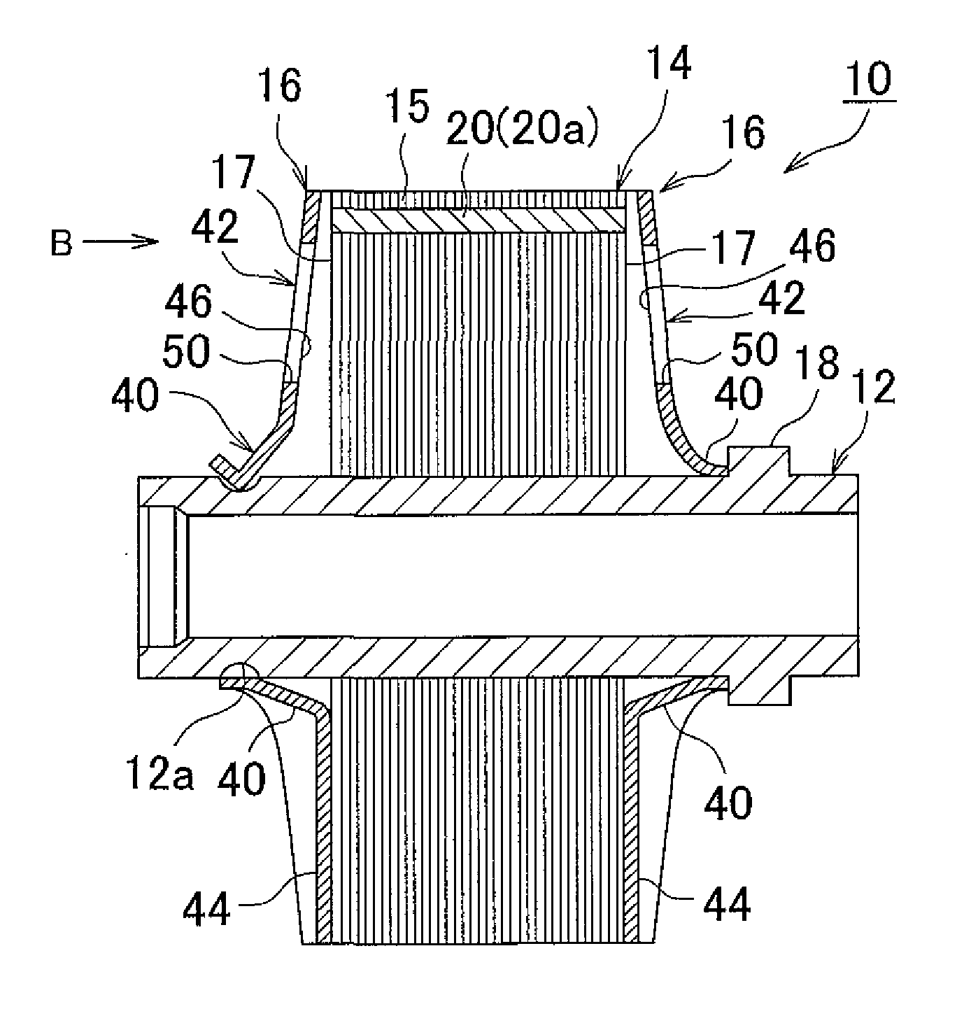
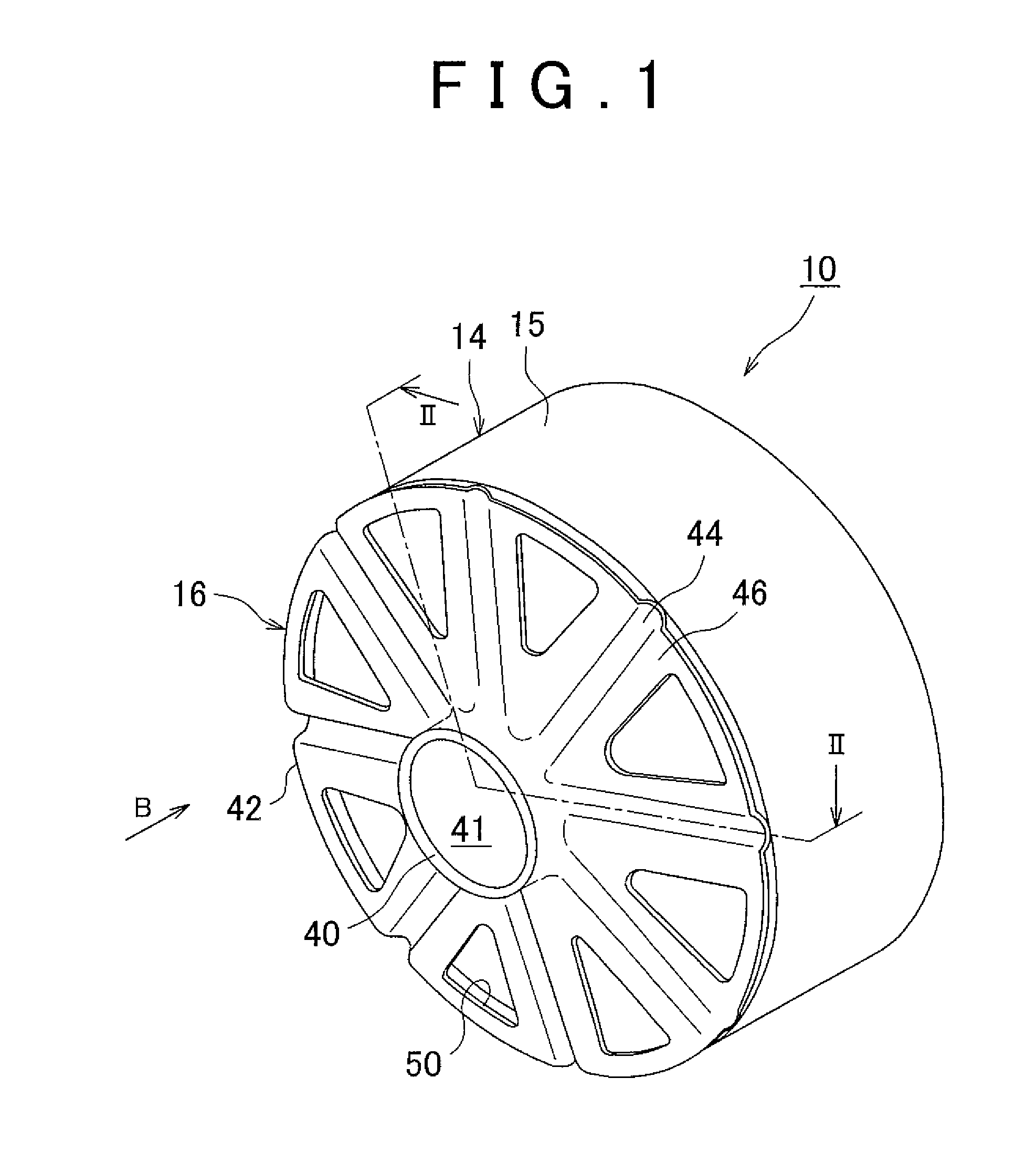
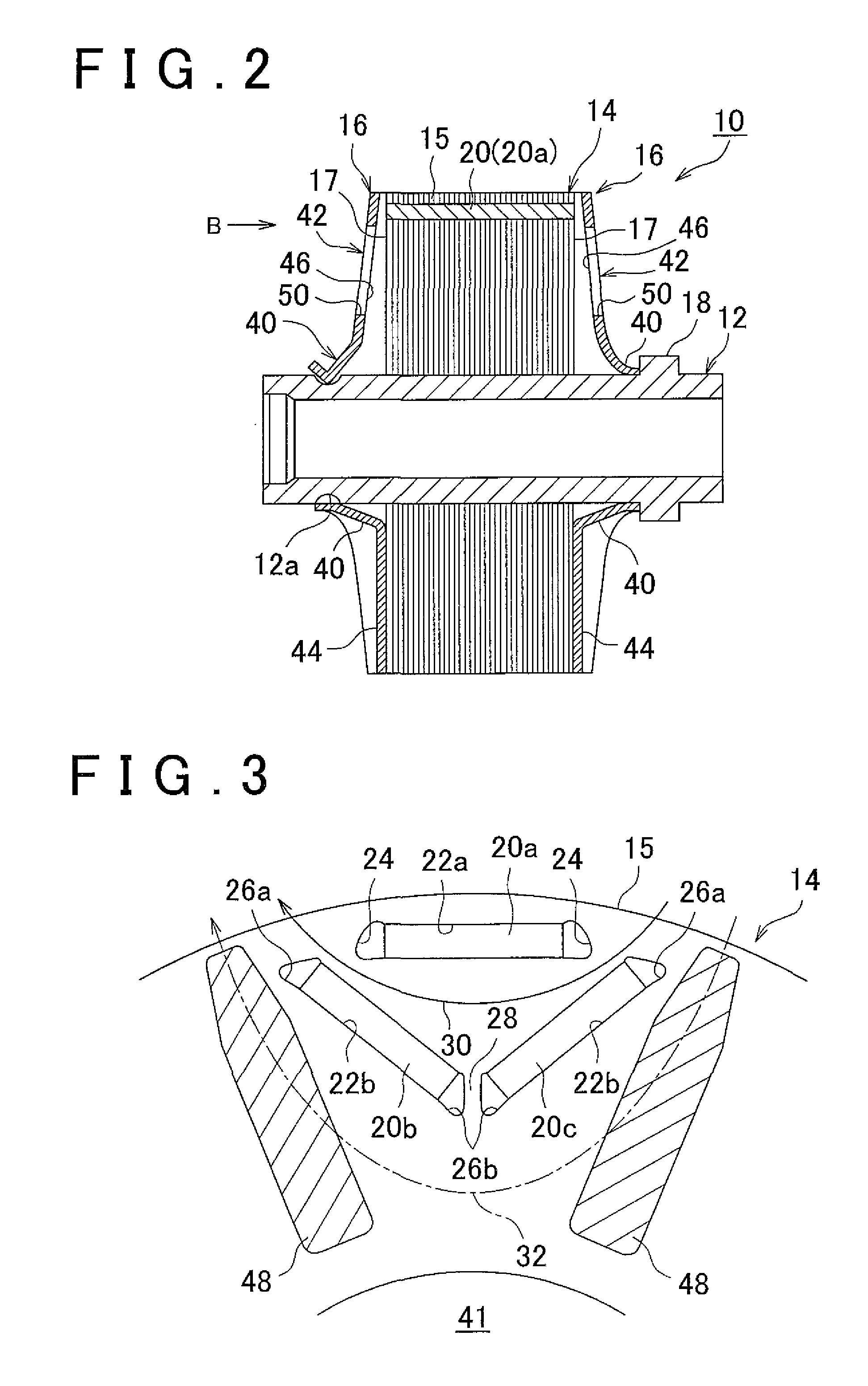
[0028]FIG. 1 is a perspective view showing a rotor 10 for a rotary electric machine which includes an end plate 16 of an embodiment of the invention while omitting the illustration of a rotor shaft. FIG. 1 shows only an end plate 16 that is provided on one of sides of the rotor 10 in the direction of an axis of the rotor 10. Besides, FIG. 2 is a sectional view of the rotor 10 taken along the axis direction thereof, including the illustration of a rotor shaft 12. In the description below, a direction along a rotation center axis of the rotor shaft 12 is termed “an axis direction”, and a direction orthogonal to the axis direc...


PUM


Abstract

An end plate is made of a magnetic material, and holds an axis-direction end surface of a rotor core in which a permanent magnet is buried. The end plate includes: a protruded portion constructed so as to be caused to pressingly contact the axis-direction end surface of the rotor core when mounted in the rotor; and a depressed portion constructed so as not to contact the axis-direction end surface. The protruded portion is formed so as to contact only one of a d-axis magnetic path region and a q-axis magnetic path region that are formed by the permanent magnet within the rotor core.

Description

INCORPORATION BY REFERENCE[0001]The disclosure of Japanese Patent Application No. 2010-271892 filed on Dec. 6, 2011 including the specification, drawings and abstract is incorporated herein by reference in its entirety.BACKGROUND OF THE INVENTION[0002]1. Field of the Invention[0003]The invention relates to an end plate and, more particularly, to an end plate for use in a buried permanent magnet type rotor of a rotary electric machine.[0004]2. Description of Related Art[0005]There are known rotary electric machines, such as electric motors, electricity generators, etc., each of which includes a rotor of a buried magnet type that is rotatably supported, and a hollow cylindrical stator that is disposed around the rotor, wherein the rotor is rotationally driven by rotating magnetic fields formed within the stator.[0006]The rotor usually includes a rotor shaft, and a cylindrical rotor core that is fixed to the rotor shaft. In some cases, the rotor core is formed as a steel sheet laminate...

Claims


Application Information

Patent Timeline
Patent Type & Authority Applications(United States)
IPC IPC(8): H02K1/28
CPCH02K1/28H02K1/2766
Inventor YAMAGISHI, YOSHITADAUKAI, YOSHIHIKO
Owner TOYOTA JIDOSHA KK
Why Eureka
Try Eureka