Object detection apparatus

Inactive Publication Date: 2012-06-07
FUJITSU GENERAL LTD
View PDF12 Cites 31 Cited by
  • Summary
  • Abstract
  • Description
  • Claims
  • Application Information

AI Technical Summary

Benefits of technology

[0034]Since the object detection can be performed by using the parameter appropriate to the camera which obtains the captured image, the detection accuracy in detecting an object can be further improved.
[0035]Therefore, the object

Problems solved by technology

Moreover, an obstacle in the vicinity of the vehicle may cause difference in detection capability among the multiple cameras. FIG. 4 illustrates difference in fields of view (FOV) between the front camera and a side camera.
As a result, when the captured image captured by the right-side camera is used, an object at a long distance cannot be detected.
As described above, the speed of the vehicle may cause difference in detection capability among the multiple cameras.
Moreover, the speed of the object may affect on the detection capabil

Method used


Image

  • Object detection apparatus
  • Object detection apparatus
  • Object detection apparatus

Examples


Example

1. First Embodiment>

1-1. System Configuration

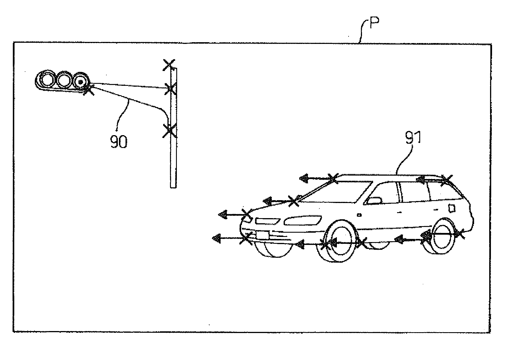
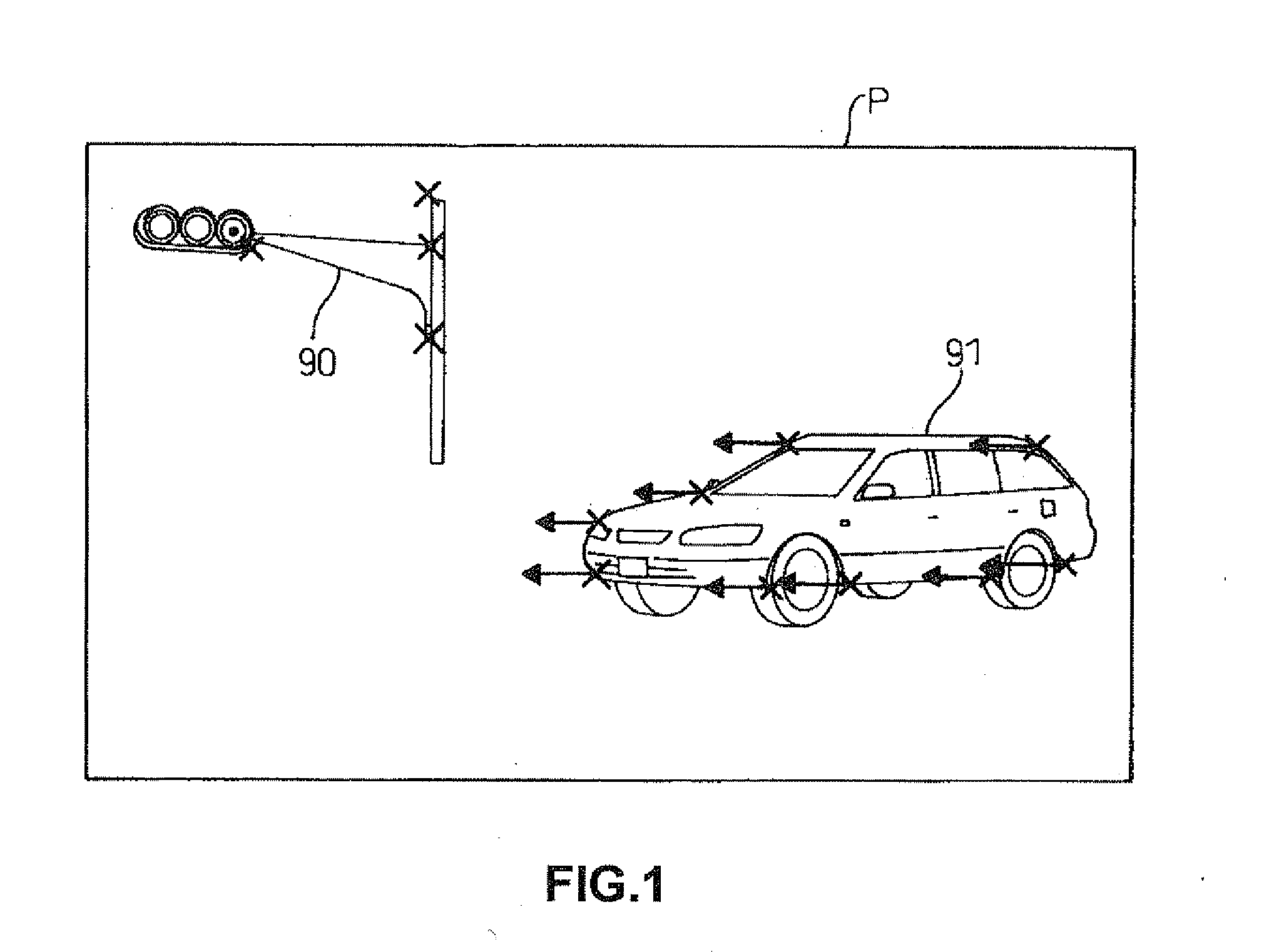
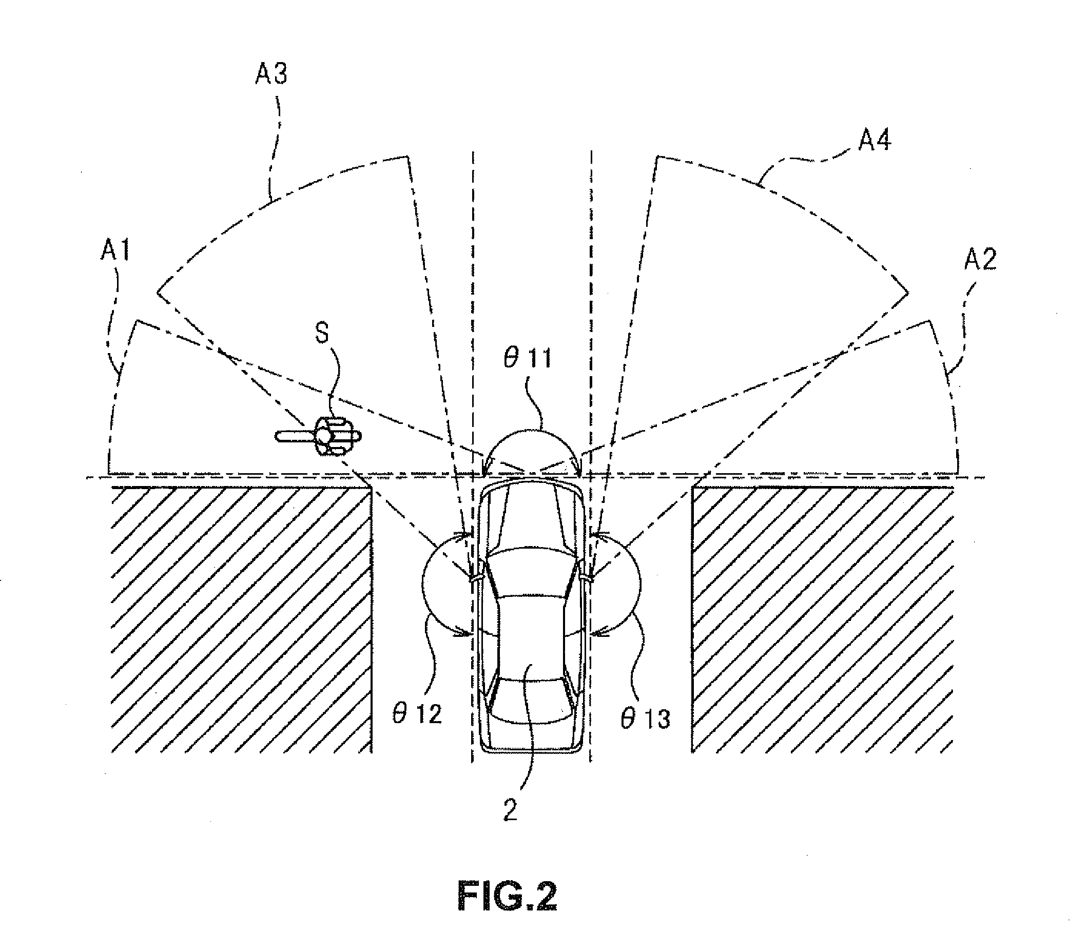
[0083]FIG. 6 is a block diagram illustrating a first configuration example of an object detection system 1. The object detection system 1 is installed on a vehicle (a car in this embodiment) and includes a function of detecting an object making a specific movement relative to the vehicle based on images captured by cameras disposed respectively at multiple locations on the vehicle. The object detection system 1 includes a function of detecting an object approaching relatively to the vehicle. However, the technology described below can be applied to a function of detecting an object making another specific movement relative to the vehicle.

[0084]As shown in FIG. 6, the object detection system 1 includes an object detection apparatus 100 that detects an object approaching the vehicle based on a captured image captured by a camera, multiple cameras 100a to 100x that are disposed separately from each other on the vehicle, a navigation apparatu...

Example

2. Second Embodiment

[0124]Next described is another embodiment of the object detection system 1. FIG. 12 is a block diagram illustrating a second configuration example of the object detection system 1. The same reference numerals are used to refer to the same structural elements as the structural elements described, referring to FIG. 6, in the first configuration example. Structural elements having the same reference numerals are the substantially same unless otherwise explained. Moreover, other embodiments may include structural elements and functions described below in the second configuration example.

[0125]An ECU 10 includes multiple object detectors 13a to 13x of which number is the same as the number of multiple cameras 110a to 110x. The object detectors 13a to 13x respectively correspond to the multiple cameras 110a to 110x. Each of the object detectors 13a to 13x performs the detection process based on a captured image captured by the corresponding camera. Functions of each o...

Example

3. Third Embodiment

[0131]Next described is another embodiment of the object detection system 1. FIG. 13 is a block diagram illustrating a third configuration example of the object detection system 1. The same reference numerals are used to refer to the same structural elements as structural elements described, referring to FIG. 6, in a first configuration example. Structural elements having the same reference numerals are the substantially same unless otherwise explained. Moreover, another embodiment may include structural elements and functions described below in the third embodiment.

[0132]An object detection apparatus 100 in this configuration example includes two object detectors 13a and 13b, two image selectors 30a and 13b, and two trimming parts 14a and 14b fewer than the number of multiple cameras 110a to 110x. The two trimming parts 14a and 14b are implemented by arithmetic processing performed by a CPU of an ECU 10, based on a predetermined program.

[0133]The image selectors ...


PUM


Abstract

A parameter memory of an object detection apparatus retains a plurality of parameters used for a detection process for each of a plurality of detection conditions. A parameter selector selects a parameter from amongst the parameters retained in the parameter memory, according to an existing detection condition. Then an object detector performs the detection process of detecting an object approaching a vehicle, based on a captured image captured by a camera out of a plurality of cameras disposed at different locations of the vehicle, by using the parameter selected by the parameter selector.

Description

BACKGROUND OF THE INVENTION[0001]1. Field of the Invention[0002]The invention relates to a technology that detects an object in a vicinity of a vehicle.[0003]2. Description of the Background Art[0004]An obstacle detection apparatus for a vehicle has been conventionally proposed. For example, a conventional obstacle detection apparatus includes: a left camera and a right camera that are provided respectively on a left side and a right side of a vehicle, facing forward from the vehicle, and that capture images of areas at a long distance; and a center camera that is provided between the left and the right cameras to capture images of a wide area at a short distance. The obstacle detection apparatus includes: a left A / D converter; a right A / D converter; and a center A / D converter; each of which receives outputs from the left, the right and the center cameras; and a matching apparatus that receives outputs from the left and the right A / D converters, matches an object on both images, and...

Claims


Application Information

Patent Timeline
IPC IPC(8): G06K9/00H04N7/18
CPCG06K9/00805G06V20/58
Inventor MURASHITA, KIMITAKAYAMAMOTO, TETSUO
Owner FUJITSU GENERAL LTD
Why Eureka
Try Eureka