Automatic door closure unit

a technology of automatic door closure and closer, which is applied in the direction of door/window fittings, multi-purpose tools, construction, etc., can solve the problems of increasing the cost of the product, reducing the stability of the operation of the product, and difficulty in machining, so as to ensure the stability of the operation, improve the function of the check valve, and simple in configuration

Inactive Publication Date: 2012-06-14
WOO SAENG YOON
View PDF15 Cites 13 Cited by
  • Summary
  • Abstract
  • Description
  • Claims
  • Application Information

AI Technical Summary

Benefits of technology

[0027]According to the present invention, the automatic door closer is capable of completely preventing the oil charged thereinto from leaking to the outside, so that when disposed on a fire-proof door, it can keep fire from occurring by means of the oil leaking to the outside.
[0028]In addition, the automatic door closer has the hydraulic circuits for the oil moving between the first and second chambers at the time when the door is open and closed in such a manner as to be formed independently of each other, through the damper housing and the activating shaft, which is unlike the conventional practice, thereby ensuring the stability of the operation thereof, improving the function of the chec

Problems solved by technology

By the way, the conventional automatic door closers are configured wherein so as to control a door closing speed, a hydraulic circuit for adjusting an amount of oil and a hydraulic circuit of a check valve are operated cooperatively to each other, thereby making it difficult to perform the machining and raising the cost of the product.
Moreover, the two hydraulic circuits are provided in the state of being not isolated from each other and have influe

Method used


Image

  • Automatic door closure unit
  • Automatic door closure unit
  • Automatic door closure unit

Examples


Embodiment Construction

[0042]Hereinafter, an explanation on an automatic door closer according to the present invention will be in detail given with reference to the attached drawings.

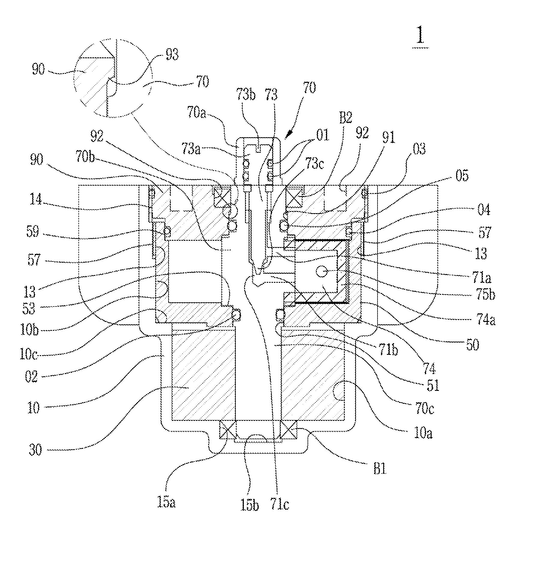
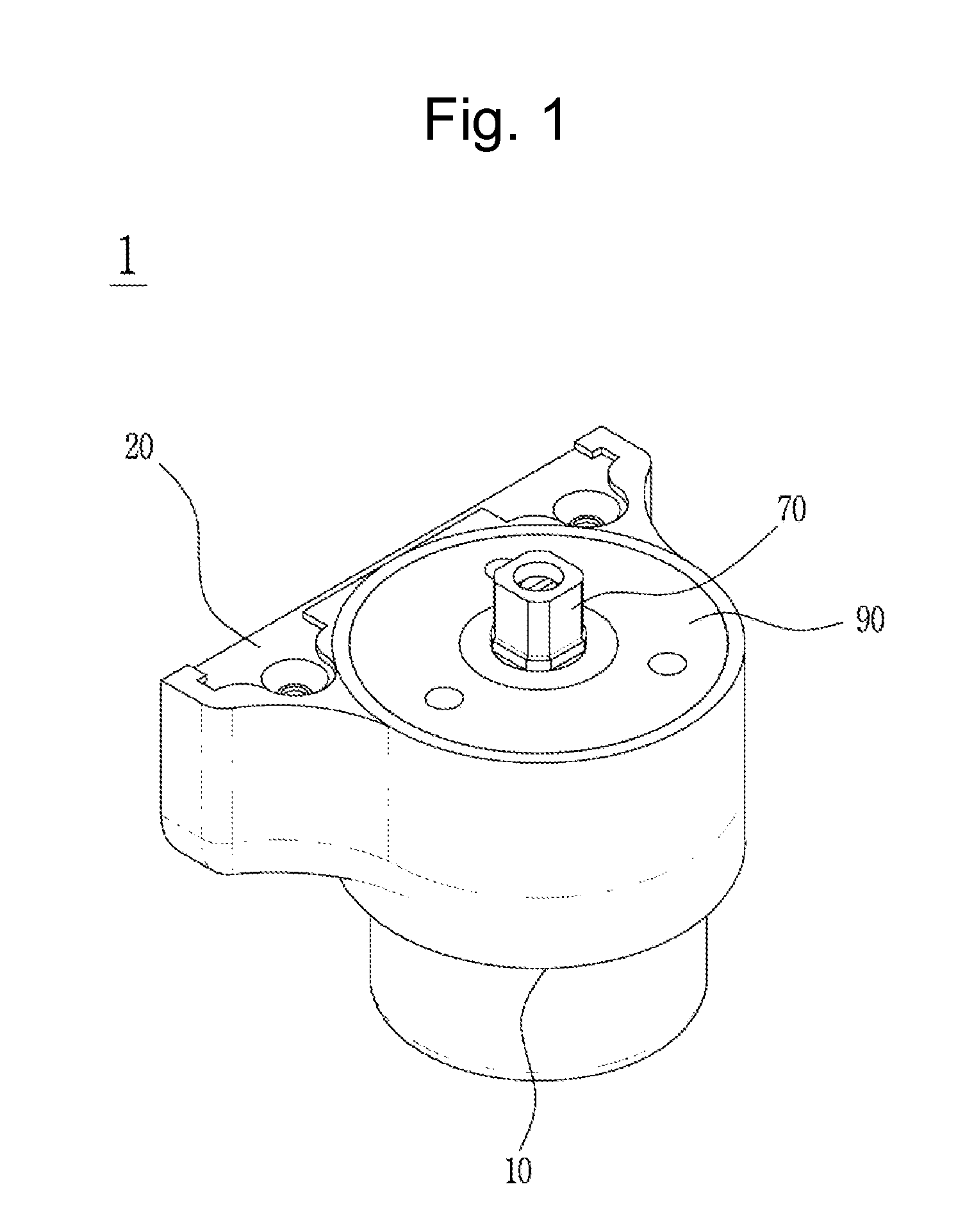
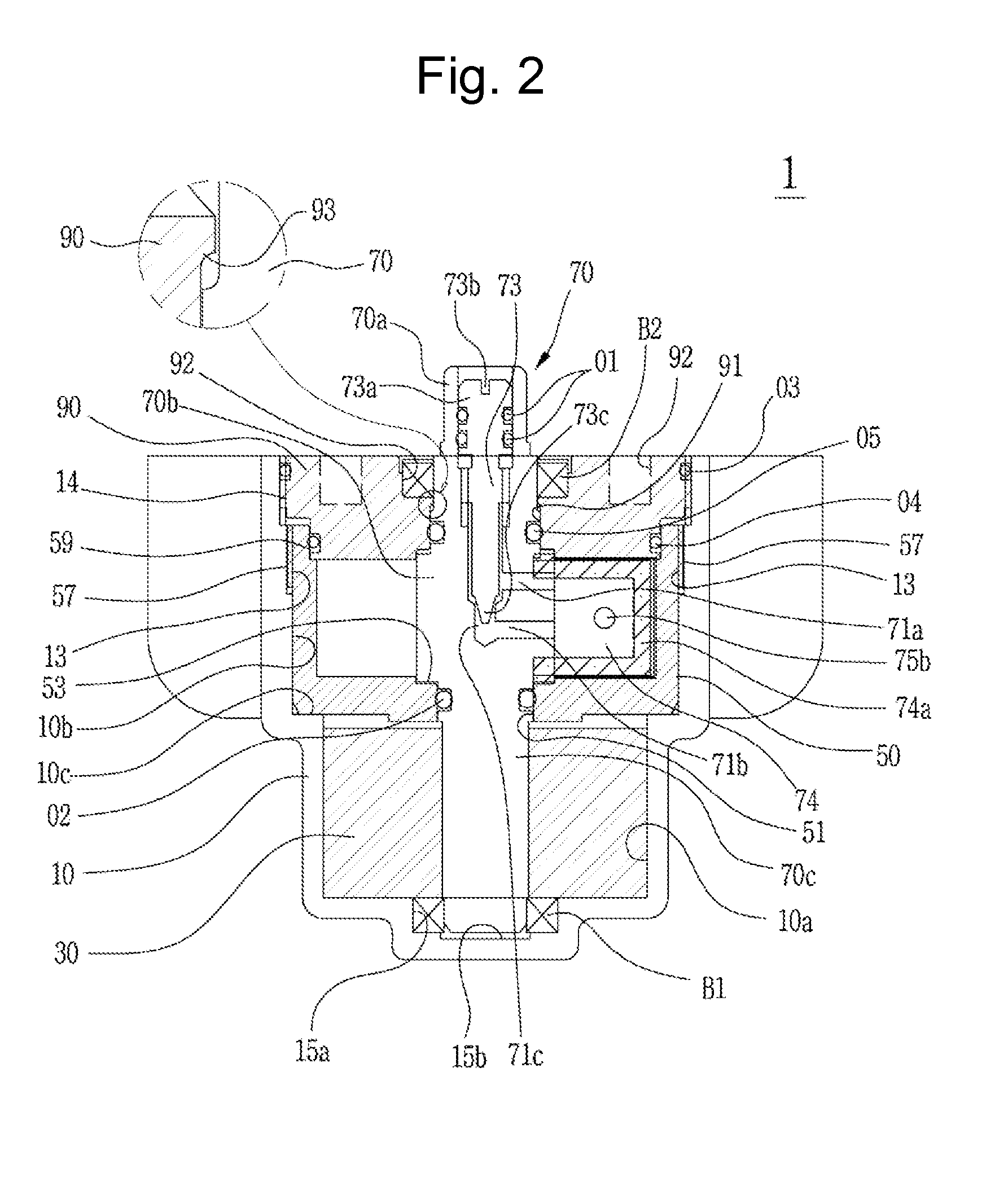
[0043]FIG. 1 is a perspective view showing an automatic door closer according to the present invention, FIG. 2 is a longitudinal sectional view showing the automatic door closer of FIG. 1, FIG. 3 is a plan view showing a state where a spiral spring is disposed on a main housing in the automatic door closer according to the present invention, FIG. 4 is a plan view showing the automatic door closer from which a cover is removed, FIG. 5 is a plan view showing a damper housing in the automatic door closer according to the present invention, FIG. 6 is a schematic view showing open positions of a door corresponding to the delaying sections and the accelerating sections of door closing speeds indicated in FIG. 5, and FIGS. 7 and 8 are sectional views showing an activating shaft in the automatic door closer according to the present ...


PUM


Abstract

The present invention relates to an automatic door closer including: a main housing having the shape of a cylinder; a damper housing adapted to divide the interior of the main housing into an upper chamber and a lower chamber and having oil charged thereinto and a fixed vane formed at one side of the inner peripheral surface thereof in such a manner as to be projected toward the center thereof; a cover fixedly coupled to the upper periphery of the main housing; an activating shaft having one end extended to the outside through the cover in such a manner as to be rotatably supported and the other end rotatably supported against the bottom surface of the main housing through the damper housing; a rotary vane formed integrally to the outer periphery of the activating shaft so as to divide the interior of the damper housing into first and second chambers, together with the fixed vane; a return spring adapted to provide a returning force of returning the activating shaft to an initial setting position at the time when the door is closed; and damping means adapted to selectively provide a damping function if the activating shaft and the rotary vane are rotated in a closing direction of the door.

Description

TECHNICAL FIELD [0001]The present invention relates to an automatic door closer unit, and more particularly, to an automatic door closer that is simple in configuration, thereby making it easy to perform its machining, and that has hydraulic circuits, through which oil is guided at the time when a door is open and closed, provided independently of each other, thereby ensuring good stability in operation and preventing the oil charged into the inside from leaking to the outside.BACKGROUND ART[0002]Generally, a door closer is an automatic door closing device that is installed on a large-sized steel door like a fire-proof door and is automatically returned slowly to its original position after the door is open.[0003]Conventional automatic door closers have various structures in accordance with the kinds of door. Among them, there has been proposed Korean Patent No. 446221 issued to the same applicant as the present invention, which discloses an automatic door closer having a compact vo...

Claims


Application Information

Patent Timeline
IPC IPC(8): E05F3/10
CPCE05F3/12E05F3/14E05F3/20E05F2003/228E05Y2201/21E05Y2201/41Y10T16/27E05Y2201/20E05Y2201/254E05Y2900/132Y10T16/2777Y10T16/299Y10T16/2799E05Y2201/49E05F3/08E05F5/02
Inventor WOO, SAENG YOON
Owner WOO SAENG YOON
Why Eureka
Try Eureka