Method for manufacturing power socket

Inactive Publication Date: 2012-06-14
SOLTEAM ELECTRONICS
View PDF1 Cites 0 Cited by
  • Summary
  • Abstract
  • Description
  • Claims
  • Application Information

AI Technical Summary

Benefits of technology

[0008]The main objective of the present invention is to provide a method for manufacturing a power socket in order to manufacture the power socket that has: at least two metal pins, one end of each of the integrally-formed metal pins being defined as a solid round-column shaped contact section and the other end thereof being defined as a flat terminal section, the terminal section and the contact section being integrally formed in one piece, instead of being connected via riveting which may loose and cause dangers; and an insulating seat member. Hence an anticipated structural strength is also achieved, and the safety use is ensured and the service life of the power socket is prolonged.
[0009]The second objective of the present invention is to provide the method for manufacturing the power socket so as to achieve that the metal pin manufactured by the manufacturing method provided by the present invention has the advantages of saving materials, fast in formation, and the automatic punching formation mold adopted by the present invention increasing the production rate.

Problems solved by technology

The disadvantage of the hollow metal pin is that the hollow metal pin is made via a rolling formation, so the strength of the hollow metal pin is not strong enough and is easily to be deformed.
With the raising costs of the metal sheets, the formation of the hollow metal pins result in an issue of wasting materials, and the manufacturing cost is therefore increased.
In fact, serious disadvantages of both of a hollow metal pin and a hollow metal pin provided in an insulating column are that the thickness is not enough so the voltage endurance and the current endurance are obviously not enough and can not pass the safety regulation.
Beside, for manufacturing the solid contact pin, operation procedures of cutting and riveting are increased and result in a higher production cost for preventing the solid contact pin 20 from loosing, a blocking ring 201 having a larger outer diameter is radially provided to the solid contact pin 20, and the outer diameter of the blocking ring 201 is the original outer diameter of the solid metal round-column shaped member; the solid contact pin 20 and the blocking ring 201 are made via cutting the original solid metal round-column shaped member, and the amount of the cut-off material is about 40% thus the production cost is hard to be reduced.
Hence, to develop a method for manufacturing an advanced power socket is the most important issue for the skilled persons in the art.

Method used


Image

  • Method for manufacturing power socket
  • Method for manufacturing power socket
  • Method for manufacturing power socket

Examples


Embodiment Construction

[0032]Following preferred embodiments and figures will be described in detail so as to achieve aforesaid objects.

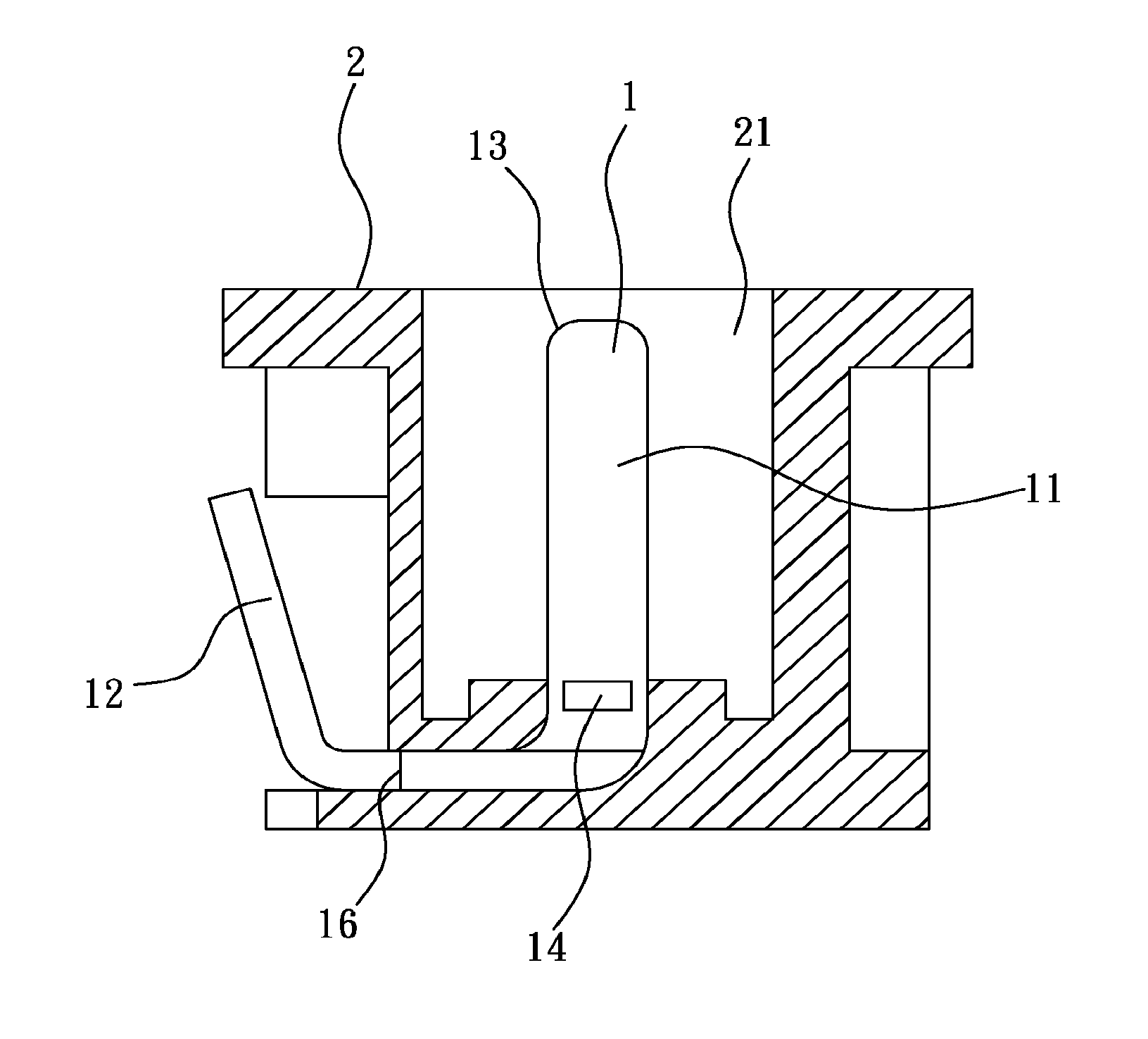
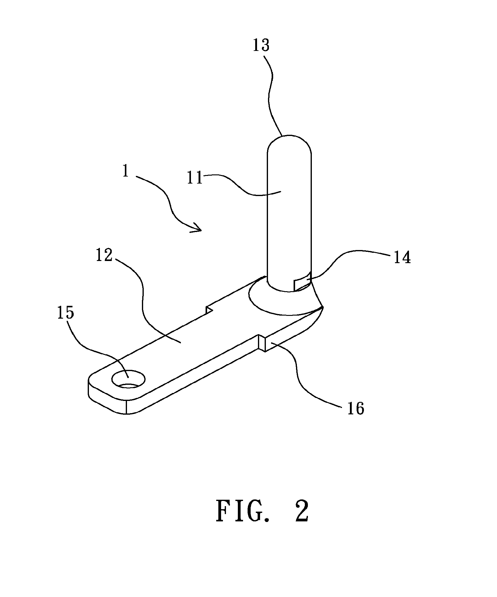
[0033]As shown from FIG. 2 to FIG. 4, which are a 3D-view of a first preferred embodiment of a metal pin used in a power socket of the method for manufacturing the power socket of the present invention, a cross sectional view of the power socket having the metal pin shown in FIG. 2 of the method for manufacturing the power socket of the present invention and a 3D-view of the power socket shown in FIG. 3 of the method for manufacturing the power socket of the present invention. The power socket provided by the present invention is composed by at least two metal pins 1 and an insulating seat member 2.

[0034]Each of the metal pins 1 is integrally formed by punching and bending a solid round-column shaped metal wire, so one end of each of the metal pins 1 is defined as a solid round-column shaped contact section 11, the other end thereof is defined as a flat terminal section 1...


PUM

PropertyMeasurementUnit
Currentaaaaaaaaaa

Abstract

A method for manufacturing a power socket is disclosed as that the power socket has at least two metal pins and an insulating seat member, wherein one end of each of the integrally-formed metal pin is defined as a solid round-column shaped contact section and the other end thereof is defined as a flat terminal section, the terminal section and the contact section are integrally formed in one piece.

Description

BACKGROUND OF THE INVENTION[0001]1. Field of the Invention[0002]The present invention generally relates to a method for manufacturing a power socket, more particularly to a method for manufacturing a power socket that has at least two metal pins and an insulating seat member, wherein one end of each of the integrally-formed metal pins is defined as a solid round-column shaped contact section and the other end thereof is defined as a flat terminal section, the terminal section and the contact section are integrally formed in one piece.[0003]2. Description of the Prior Art[0004]Power sockets are commonly used in electronic goods, e.g. a portable audio player or a DVD player, or in information products such as a computer, a power wire whose two ends are both sockets is used and the two ends are respectively plugged into a power socket of a product and a socket of public electricity, so the power is provided to the product and a user can therefore operate the product.[0005]The must have...

Claims


Application Information

Patent Timeline
IPC IPC(8): H01R43/20
CPCH01R43/16Y10T29/49208H01R43/20
Inventor HO, YING-SUNGYEH, TA-FENGWANG, YU-CHIEH
Owner SOLTEAM ELECTRONICS
Why Eureka
Try Eureka