Foldable Composite Tubular Structure

a composite tubular and folding technology, applied in the field of tubular structures, can solve the problems of reducing mechanical performance, reducing collapse resistance, and taking advantage of the complete steel section, and achieve the effect of facilitating the deployment of composite tubulars

Inactive Publication Date: 2012-06-14
NOBILEAU PHILIPPE CONSTANT
View PDF8 Cites 20 Cited by
  • Summary
  • Abstract
  • Description
  • Claims
  • Application Information

AI Technical Summary

Benefits of technology

[0008]One purpose of the invention is to facilitate the deployment of a composite tubular as a wellbore casing by circulating the hardening material when most of the composite tubular structure is still on the rig floor winded on a reel, ready to be lowered into the well.

Problems solved by technology

New methods for installation of tubular structures in well have recently been introduced like mono-diameter / mono-bore casing systems but have reduced mechanical performances, mostly in collapse resistance.
The patent U.S. Pat. No. 7,159,666 of the applicant, offers a solution to improve the collapse resistance, but at the expense of substantial complications in the installation and without taking advantage of the complete steel section.
However, beyond a certain pipe diameter, the dimensions of the necessary spool to store the pipe become prohibitive, as well as the necessary equipment for its unwinding.
In well casing, the road size constraints and the requirements to locate big size spool on rigs make this solution less attractive if not impossible.

Method used


Image

  • Foldable Composite Tubular Structure
  • Foldable Composite Tubular Structure
  • Foldable Composite Tubular Structure

Examples


Embodiment Construction

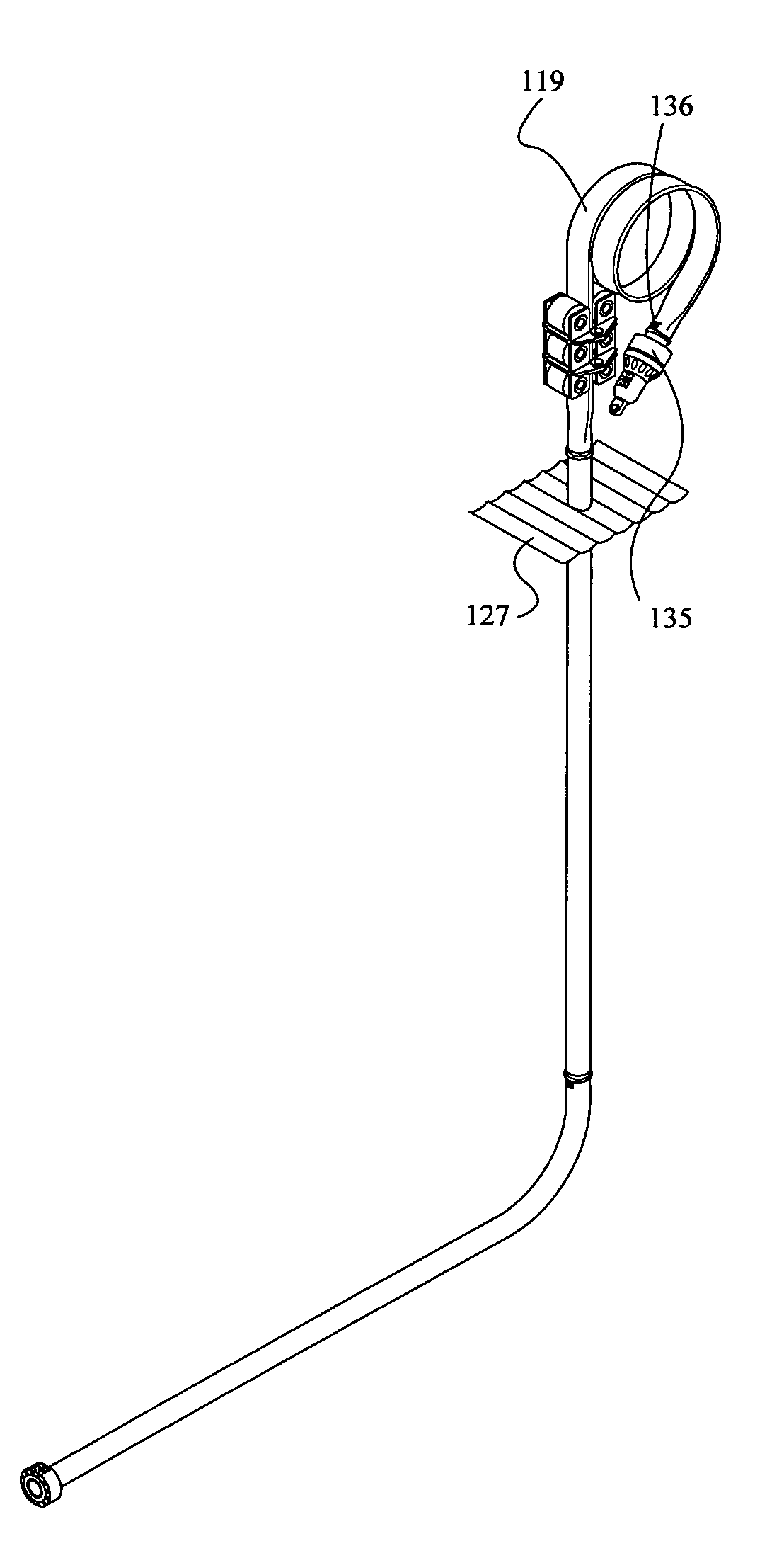
[0026]It is to be understood that the tubular structure described here comprises any tubular structure not having to be straight and possibly having a variable section. For instance, the tubular structure can have a conical portion or create a pipe embranchment as it is the case in a junction from which a main pipe splits into two or several pipes.

[0027]To make the understanding of the following description easier, we will use the term longitudinal when it is parallel to the direction of the tubular structure, and the term radial to indicate that it is somewhat in the plan perpendicular to the direction of the tubular structure. For casing applications, acknowledging that the string went down in the well vertically, we will use top, bottom, downward, upward, upper or lower.

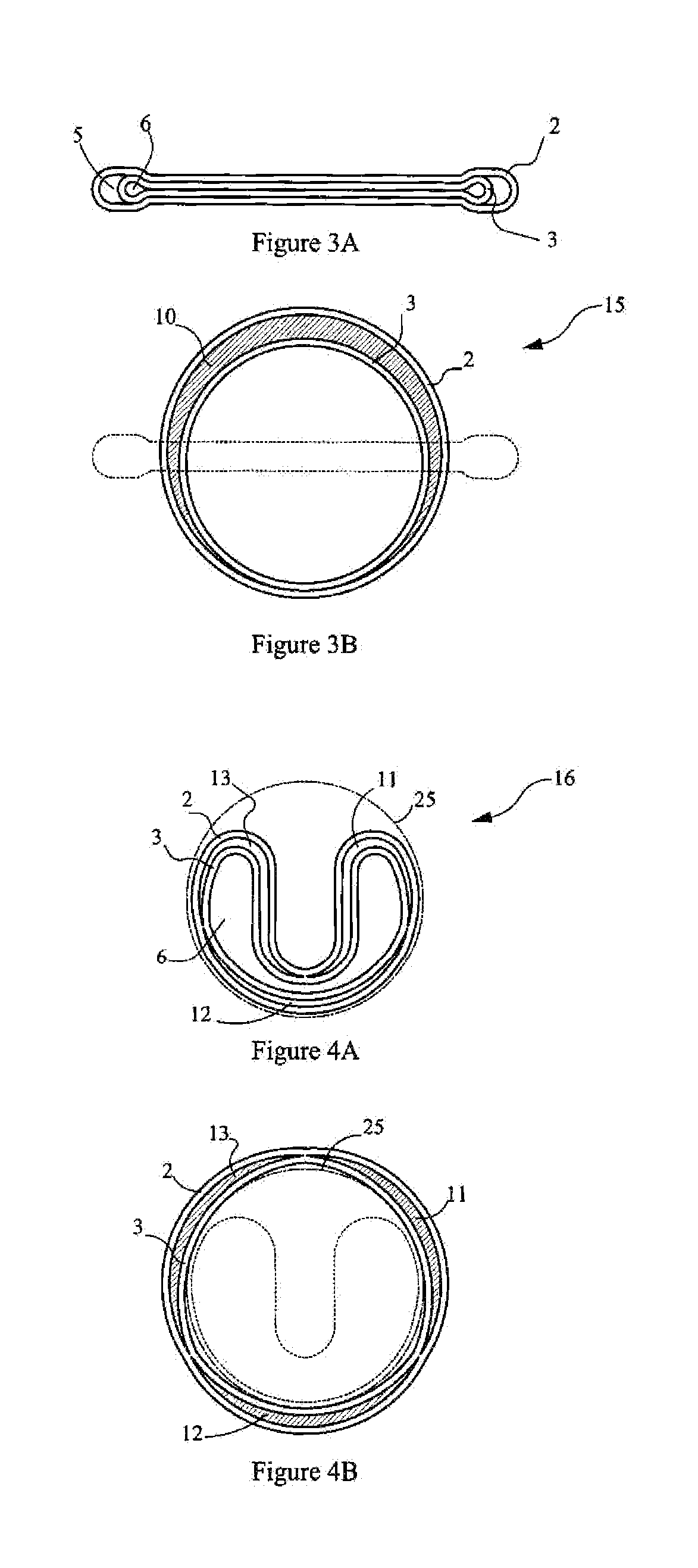
[0028]A composite tubular structure is represented in reference to FIGS. 1A, 1B and 1C. The installation of a structure, which could either be a pipeline / flowline or a downhole casing as in the present description...


PUM


Abstract

Foldable pipe-in-pipe composite tubular structure having between pipes after rounding and hardening a filling material associating the layers to enhance the structure mechanical performance mostly in collapse resistance. Improvements are related to increase foldability by having at least one of the pipe made of two layers and in case of transportation on a reel in continuous length the capability of circulating most of the hardenable filling material when the pipe is still on the reel and in case of wellbore casing application the capability of connecting sealingly successive strings of casing

Description

CROSS-REFERENCE TO RELATED APPLICATION[0001]This application is a continuation in part of application Ser. No. 10 / 416,773 filed Oct. 8, 2001 now U.S. Pat. No. 7,490,676, a continuation in part of application PCT / IB2006 / 052738 filed Aug. 8, 2006 having a priority application FR0508438 filed Aug. 8, 2005 and a continuation in part of application Ser. No. 11 / 953,335 filed Dec. 10, 2007 now U.S. Pat. No. 8,069,900. The entire disclosures of the prior applications are incorporated herein by this reference.TECHNICAL FIELD[0002]The present invention relates to well casing and oil transportation pipeline and in particular tubular structures requiring mechanical performances enhancement mostly in collapse resistance in-situ or after installation.BACKGROUND ART[0003]New methods for installation of tubular structures in well have recently been introduced like mono-diameter / mono-bore casing systems but have reduced mechanical performances, mostly in collapse resistance.[0004]The patent U.S. Pat...

Claims


Application Information

Patent Timeline
Patent Type & Authority Applications(United States)
IPC IPC(8): E21B17/00F16L11/20
CPCE21B43/103F16L55/1654F16L55/1656F16L1/038E21B43/105E21B19/22E21B33/14E21B33/1212E21B17/14E21B17/08F16L55/1657E21B41/0042
Inventor NOBILEAU, PHILIPPE C.
Owner NOBILEAU PHILIPPE CONSTANT
Why Eureka
Try Eureka