
Twinax Cable Design for Improved Electrical Performance

a technology of electrical performance and twinax cables, applied in the direction of coaxial cables/analogue cables, cables with twisted pairs/quads, cables, etc., can solve the problems of limiting the intended bandwidth and not supporting the intended application, affecting the quality of the cable, and affecting the performance of the cabl

Active Publication Date: 2012-06-14
PANDUIT
View PDF4 Cites 25 Cited by
  • Summary
  • Abstract
  • Description
  • Claims
  • Application Information

AI Technical Summary

Benefits of technology

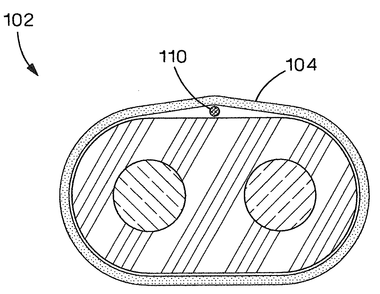
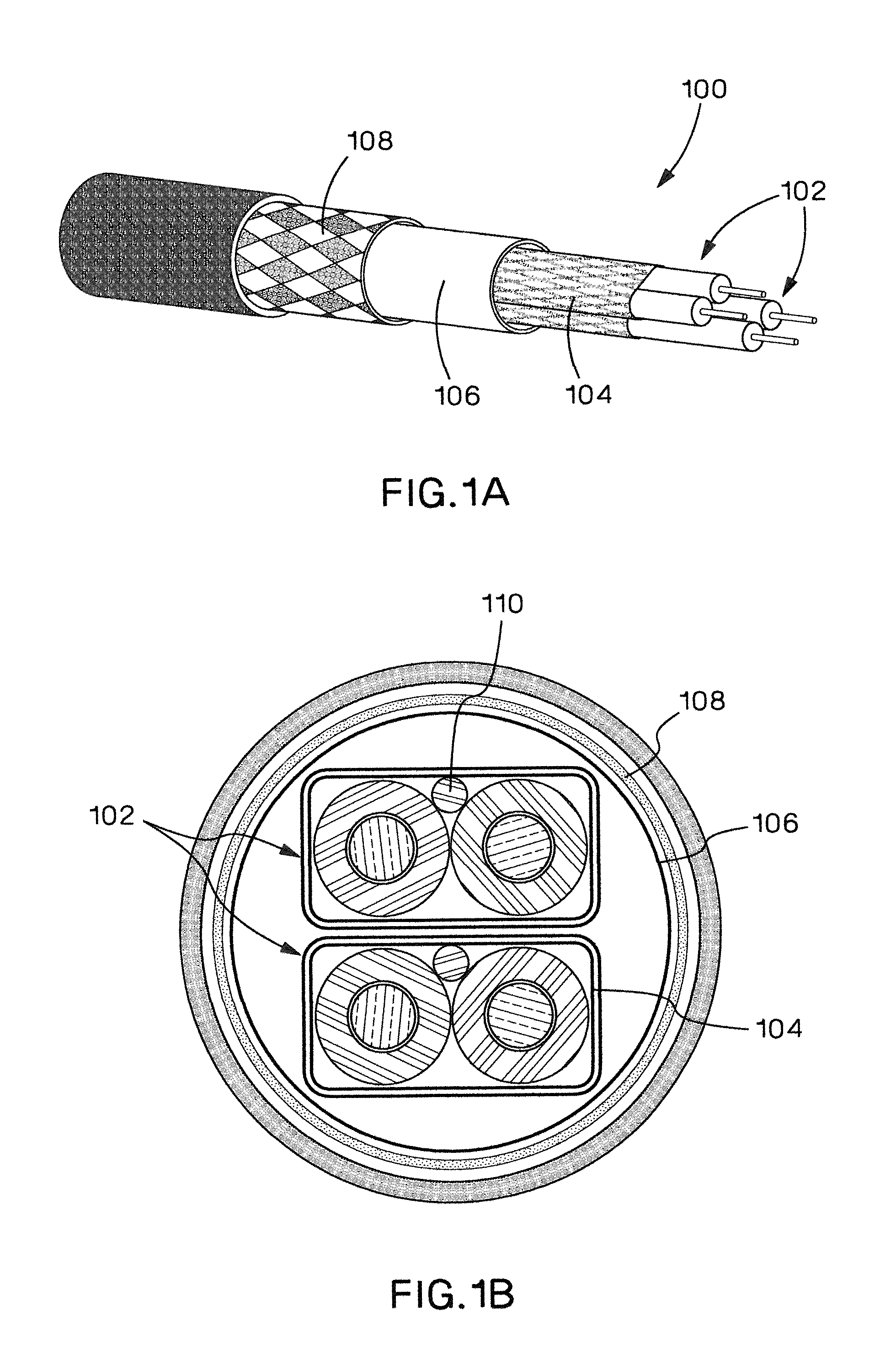
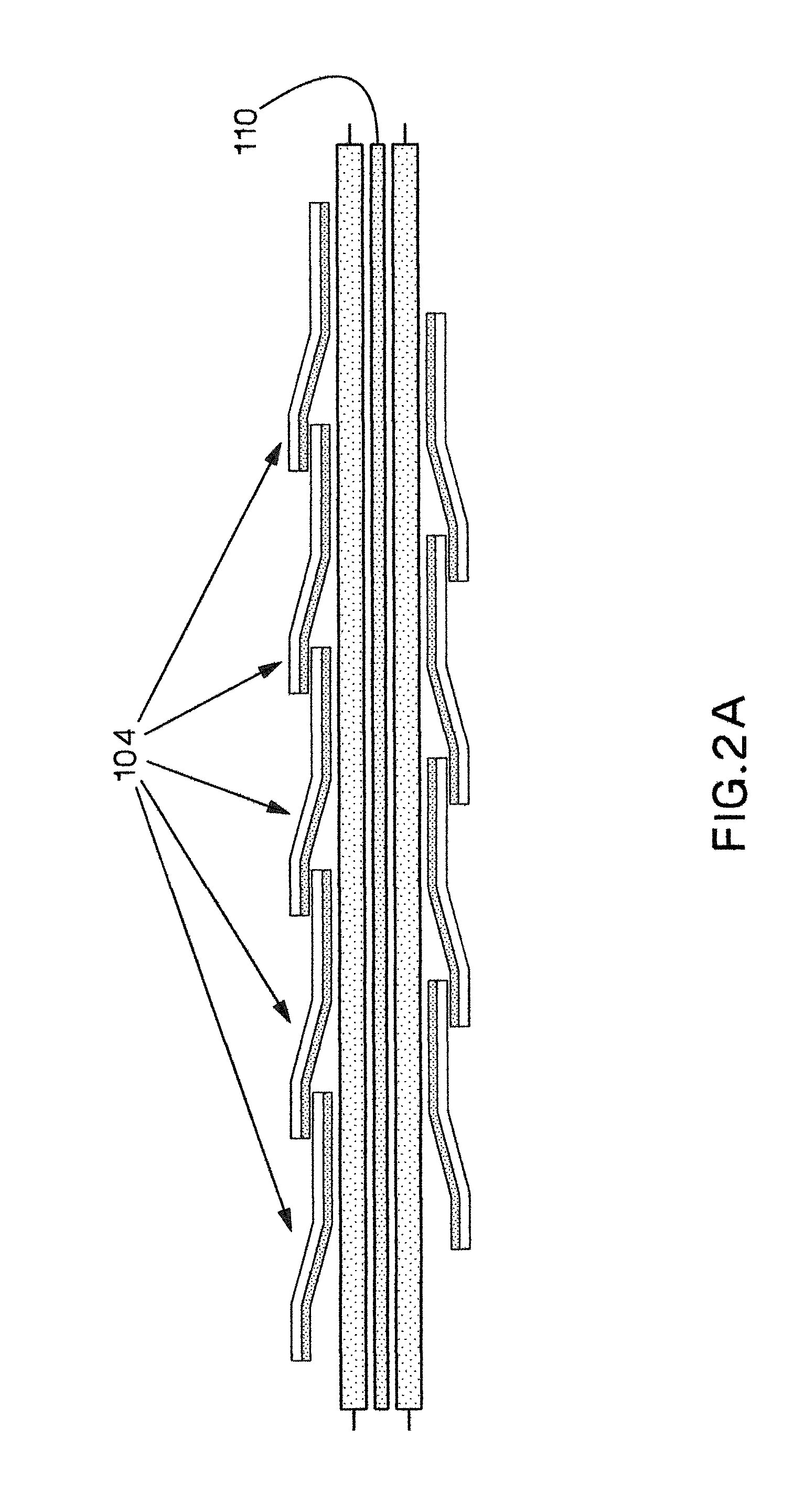
[0012]In some embodiments the two shield tapes may be wrapped in alternate directions. Th

Problems solved by technology

One of the challenges of a twinax wire-pair is that the shield tape that surrounds the twinax wire-pair can interact with the wire-pair in a destructive fashion, producing large resonant spikes (in its transfer function response) that can restrict its intended bandwidth and not support the intended application.
A drawback is media analog bandwidth.
A disadvantage of the spiral wrapped shield is that a resonance can occur.
A longitudinally wrapped shield over the twinax wire-pair is preferred from an electrical (differential mode propagation) standpoint because this resonance does not occur but a cable with a longitudinally wrapped shield has poorer mechanical properties, such as separation of pairs during bending resulting in a change of impedance and higher return loss.
From a common mode propagation viewpoint, the longitudinally wrapped twinax cable has a lower attenuation which can be problematic due to mode conversion within the cable or within the connector.
When a high frequency low impedance connection is not made (lower views in FIG. 2C), the return loss is increased which can lower the performance of the cable 100.
The problem is that the shield current does not exclusively follow the EM wave that is traveling longitudinally down the cable.
This results in an insertion loss transfer function that performs well as shown in FIG. 4C, although it also includes the aforementioned mechanical and common mode problems.

Method used


Image

  • Twinax Cable Design for Improved Electrical Performance
  • Twinax Cable Design for Improved Electrical Performance
  • Twinax Cable Design for Improved Electrical Performance

Examples


Embodiment Construction

[0042]FIG. 5 shows a longitudinal cross-sectional view of a portion of a shield tape's overlap region (A). The shield tape's longitudinal impedance has essentially two components; a spiral resistive / inductive component and a capacitive component that arises from the tape's overlap region. The overlap capacitance is controlled by the substrate thickness and the overlap width and length. In order to decrease the shield resonance magnitude and / or to increase the resonant frequency, some methods can be applied. In order to shift the resonant frequency up to higher frequencies, the over-lap to over-lap distance can be decreased. This is accomplished by having more wraps per unit length. To decrease the magnitude of the resonant spike, the overlap capacitance can be increased. One simple method of raising the capacitance (and hence lowering the impedance) is to decrease the tape's substrate thickness and / or increase the overlap length (as shown in FIG. 5A). Raising the capacitance lowers ...


PUM


Abstract

A twinax cable is described. The twinax cable has at least one twinax wire pair with a first shield tape wrapped around it and then surrounded by a second shield tape wrapped around the twinax wire pair and the first shield tape. The shield tapes are wrapped such that the metallic sides of the tape face and make contact with each other.

Description

CROSS REFERENCE TO RELATED APPLICATIONS[0001]This application claims priority to U.S. Provisional Application No. 61 / 420,833, filed Dec. 8, 2010 and entitled “TWINAX CABLE DESIGN FOR IMPROVED ELECTRICAL PERFORMANCE”, the subject matter of which is incorporated by reference in its entirety.FIELD OF THE INVENTION[0002]The present invention relates to twinax cables with improved electrical performance.BACKGROUND OF THE INVENTION[0003]The network communications industry has selected the use of twinax wire-pair cable assemblies for the transport of high data rate information. One of the challenges of a twinax wire-pair is that the shield tape that surrounds the twinax wire-pair can interact with the wire-pair in a destructive fashion, producing large resonant spikes (in its transfer function response) that can restrict its intended bandwidth and not support the intended application.[0004]For applications requiring a high data rate with low latency performance such as in Storage Area Netw...

Claims


Application Information

Patent Timeline
IPC IPC(8): H05K9/00
CPCH01B11/203H01B11/20H05K9/0081
Inventor NORDIN, RONALD A.BOLOURI-SARANSAR, MASUD
Owner PANDUIT
Learn More