Brake device for motorcycle

a brake device and motorcycle technology, applied in the direction of braking systems, cycle brakes, cycle equipment, etc., can solve the problems of difficult to ensure road clearance and susceptible limitation of the periphery of the brake pedal, and achieve the effect of reducing the limitation of the layout of other members and ensuring the necessary road clearan

Inactive Publication Date: 2012-06-14
HONDA MOTOR CO LTD
View PDF11 Cites 11 Cited by
  • Summary
  • Abstract
  • Description
  • Claims
  • Application Information

AI Technical Summary

Benefits of technology

[0010]It is accordingly an object of an embodiment of the present invention to provide a brake device for a motorcycle having

Problems solved by technology

Hei 9-164925 to a motorcycle, the operational direction (rotational direction) of the brake pedal is changed from a longitudinal direction to a vertical direction, so that the layout of parts in the periphery of the brake pedal is susceptible to limitation.
Further,

Method used


Image

  • Brake device for motorcycle
  • Brake device for motorcycle
  • Brake device for motorcycle

Examples


Embodiment Construction

[0034]A mode for carrying out the present invention will now be described with reference to the attached drawings. The orientation of each drawing is the same as that of the reference numerals included therein.

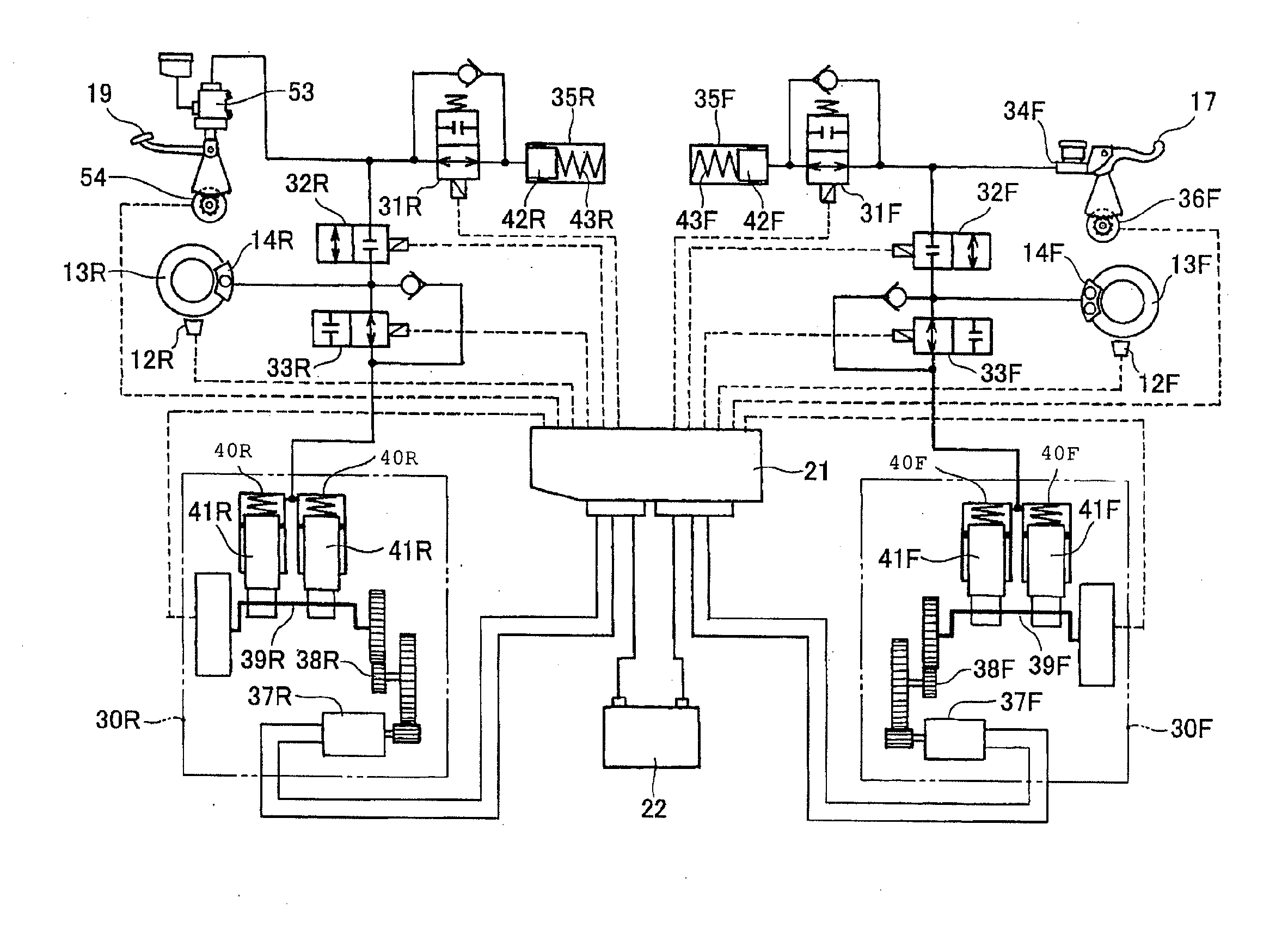
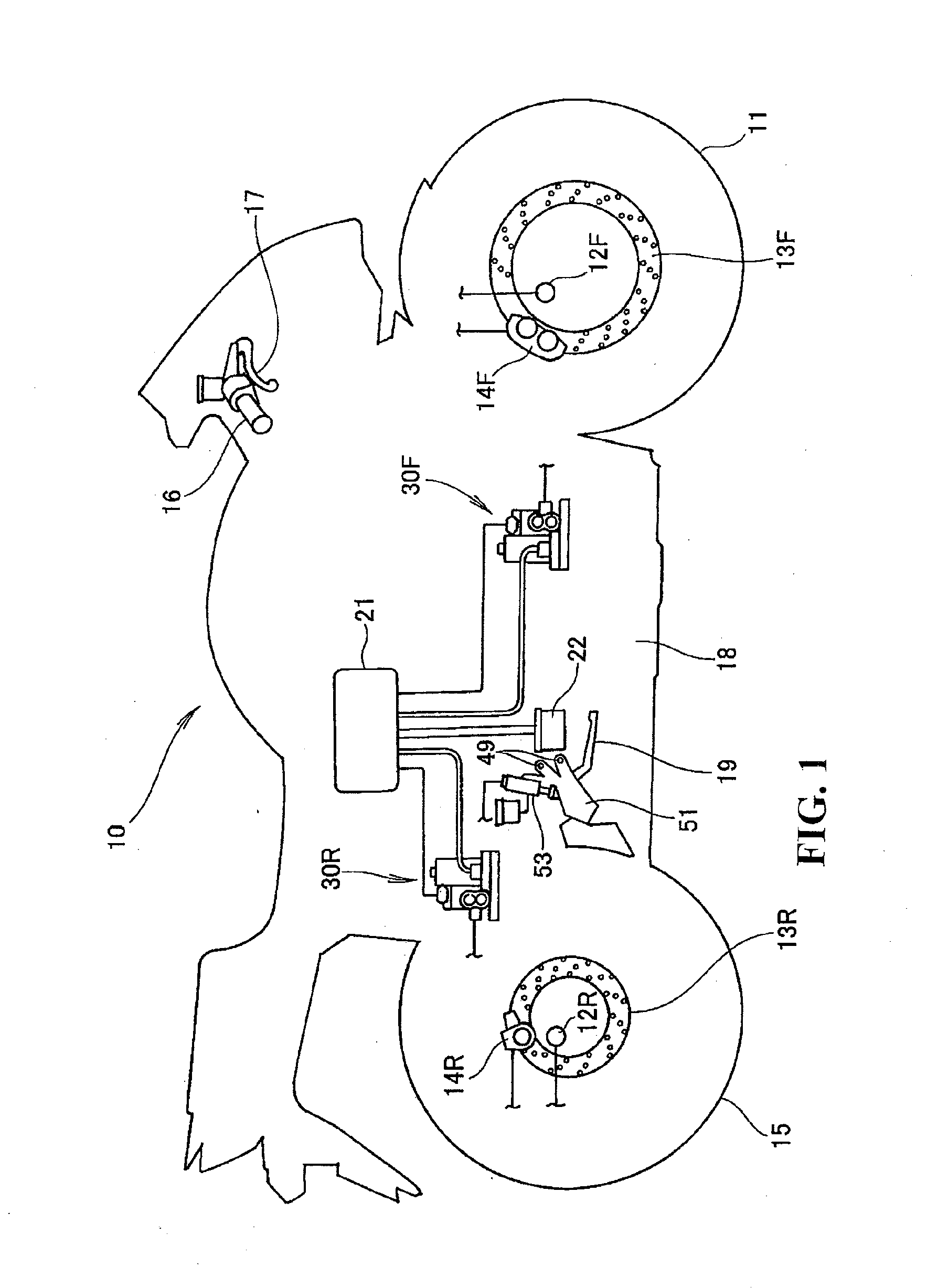
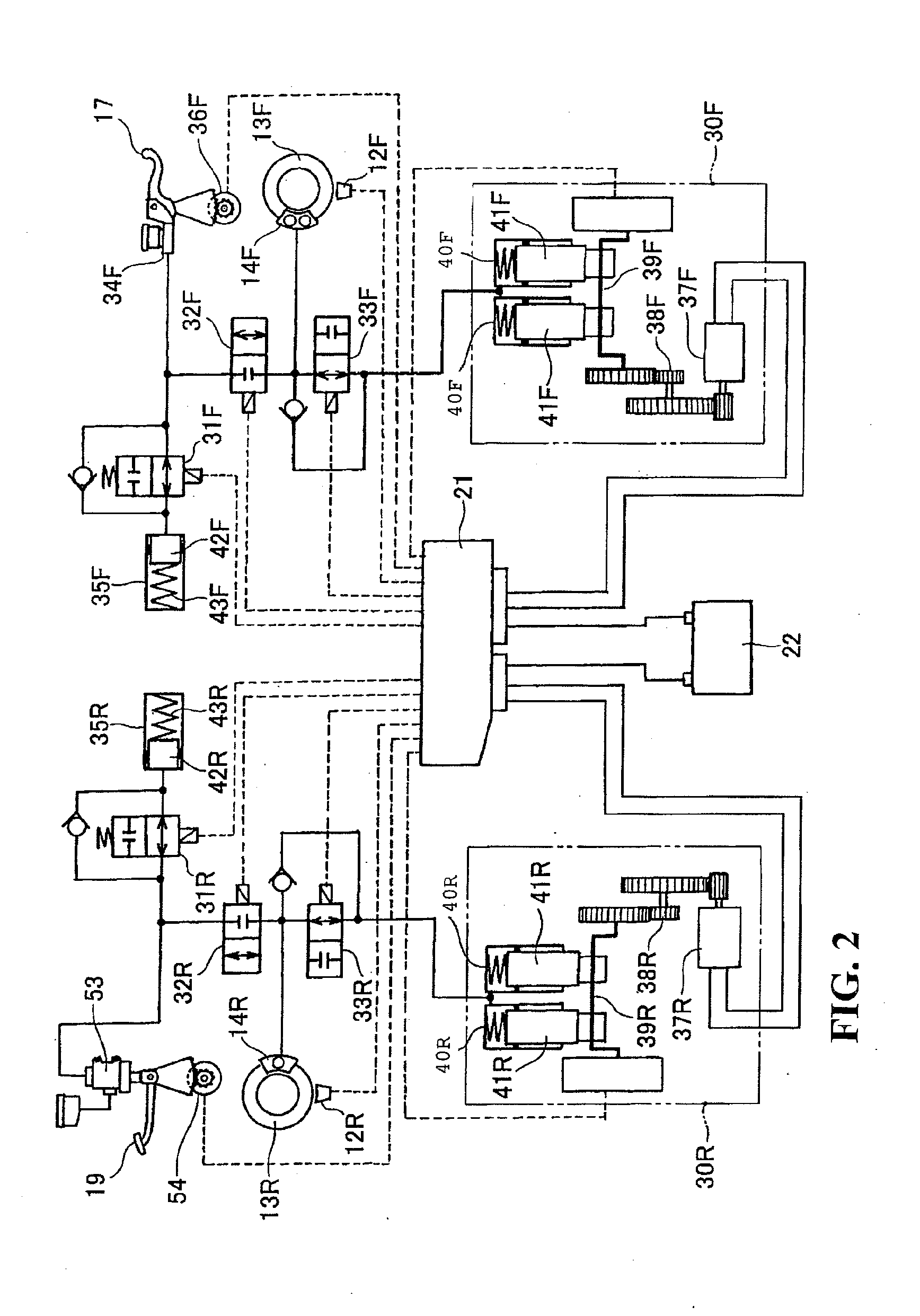
[0035]As shown in FIG. 1, a motorcycle 10 includes a front wheel 11, a rear wheel 15, a steering handle 16, and a vehicle body 18. A front wheel speed sensor 12F (F means the front side of the vehicle, and the same applies to the following), a brake disc 13F and a brake caliper 14F are provided in the vicinity of the front wheel 11. A rear wheel speed sensor 12R (R means the rear side of the vehicle, and the same applies to the following), a brake disc 13R and a brake caliper 14R are provided in the vicinity of the rear wheel 15. A brake lever 17 to be operated by an operator's hand is provided on the steering handle 16. A brake pedal 19 to be operated by an operator's foot is provided at a lower central portion of the vehicle body 18. Hydraulic modulators 30F and 30R for adju...


PUM


Abstract

A brake device for a vehicle includes a brake pedal rotatably supported on a support shaft and extending in a front ward direction from the support shaft in the longitudinal direction of the vehicle. A master cylinder is located on the rear side of the support shaft in the longitudinal direction of the vehicle for generating a braking hydraulic pressure according to the rotational operation of the brake pedal. An operational amount detector is mechanically connected to the brake pedal for detecting the rotational amount of the brake pedal. The master cylinder includes an axis that is arranged vertically and is located above the support shaft with the operational amount detector being located on the rear side of the support shaft in the longitudinal direction of the motorcycle. Thus, the master cylinder and the operational amount detector can be densely arranged in the longitudinal direction of the vehicle.

Description

CROSS-REFERENCE TO RELATED APPLICATIONS[0001]The present application claims priority under 35 USC 119 to Japanese Patent Application No. 2010-274025 filed on Dec. 8, 2010 the entire contents of which are hereby incorporated by reference.BACKGROUND OF THE INVENTION[0002]1. Field of the Invention[0003]The present invention relates to a brake device for a motorcycle including a brake pedal, a master cylinder, and an operational amount detector for detecting the rotational amount of the brake pedal.[0004]2. Description of Background Art[0005]A technique is known wherein a potentiometer is used to obtain the operational amount of a brake pedal to provide control information for an ABS (Antilock Brake System). See, for example, FIGS. 1 and 2 of Japanese Patent Laid-Open No. Hei 9-164925.[0006]As shown in FIG. 1 of Japanese Patent Laid-Open No. Hei 9-164925, a potentiometer (60) (the numbers in parentheses are the same as the numbers shown in Japanese Patent Laid-Open No. Hei 9-164925) and...

Claims


Application Information

Patent Timeline
IPC IPC(8): B62L3/04B60T11/16B60T7/04
CPCB60T7/042B60T11/16B60T11/18Y10T74/20888B60T8/3225B60T8/4081Y10T74/20528B60T8/261
Inventor NISHIKAWA, YUTAKATODA, MAKOTOTANI, KAZUHIKO
Owner HONDA MOTOR CO LTD
Why Eureka
Try Eureka