Kettle

a technology of electric kettles and kettles, applied in the field of electric kettles, can solve the problems of more complex appliances, more cumbersome proposals, and difficulty in filling an average kettle to exactly the minimum level

Inactive Publication Date: 2012-06-14
VON SEIDEL MICHAEL
View PDF2 Cites 19 Cited by
  • Summary
  • Abstract
  • Description
  • Claims
  • Application Information

AI Technical Summary

Benefits of technology

[0011]It is an object of this invention to provide a kettle that has a suitably low minimum volumetric operating volume coupled with a satisfactorily large maximum volume and that is aimed at combating, at least to some extent, the difficulty of introducing small quantities of water into it, such as for the purpose of heating a quantity of water suitable for making one or two cups of beverage.

Problems solved by technology

Added to this is the difficulty of filling an average kettle to exactly the minimum level and the tendency is always rather to add more water in order to avoid having less than the minimum.
Some of these are more complex appliances in which only a required small quantity of water is heated in a separate chamber or partition.
These proposals are therefore more cumbersome than a simple single water chamber kettle; and more costly.
In spite of the fact that there may have been limited success in achieving the objective, there remains the difficulty of reasonably accurately filling a kettle, for example with only 250 millilitres, or even 500 millilitres of water, or whatever other similar small volume is required.
The bottom of the water chamber is typically of the largest horizontal cross-sectional size of the water chamber and therefore the height or level of water that corresponds to such a small volume of water is itself small and accompanied by the difficulty mentioned above of filling the kettle to exactly the required level.
The difficulty is exacerbated by the fact that a kettle is generally hand held in midair whilst water is introduced into it, typically from a tap, and the large bottom would invariably be tilted in one direction or another thereby giving a false reading of the content through the usual transparent window or sidewall of the body that defines the water chamber.

Method used


Image

  • Kettle
  • Kettle
  • Kettle

Examples


Embodiment Construction

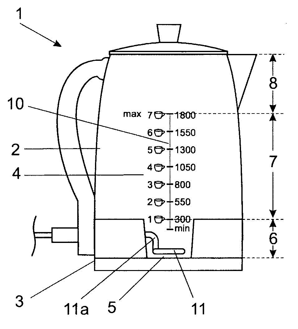
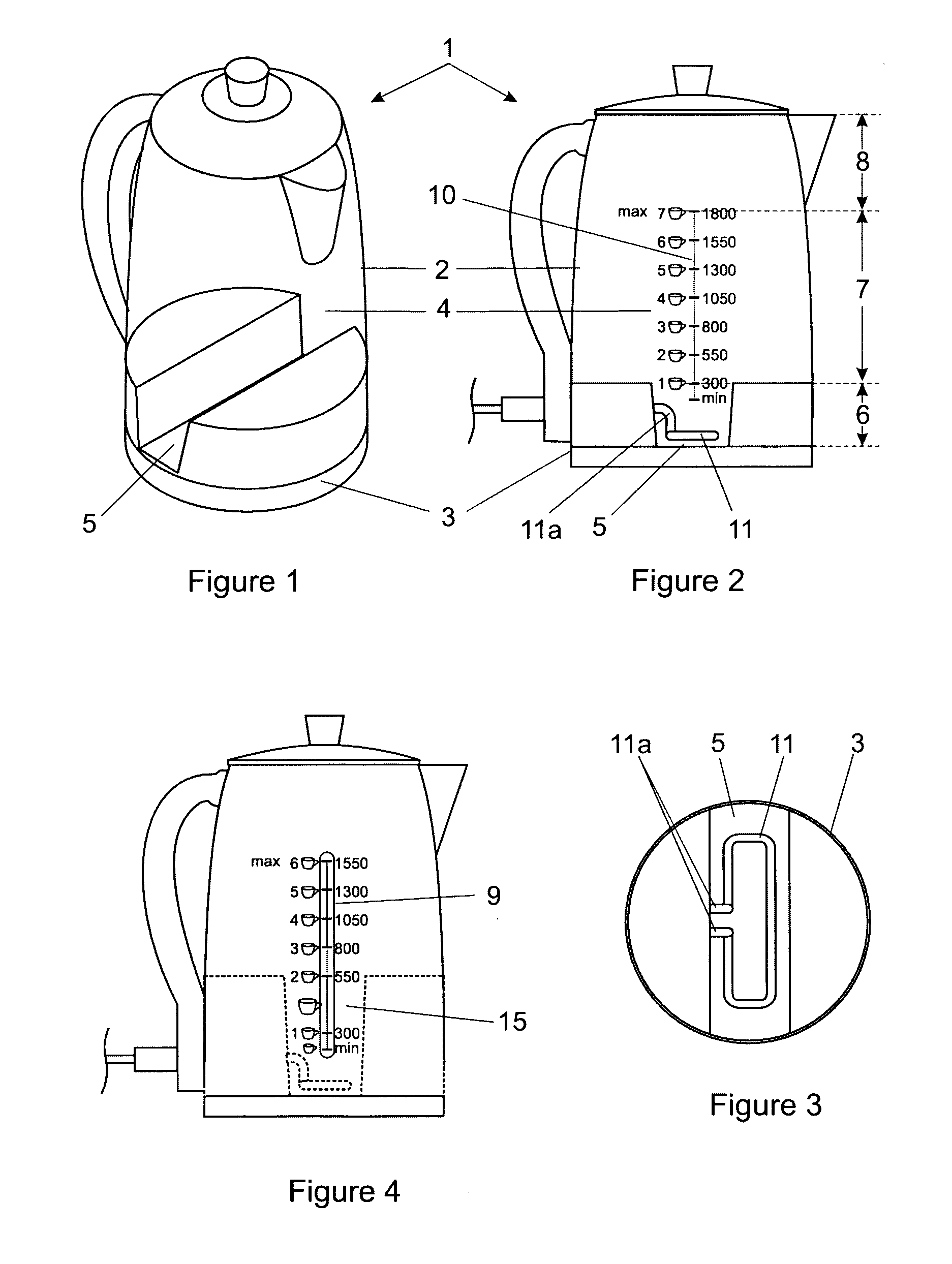
[0030]In the embodiment of the invention in FIGS. 1 to 3 a kettle (1) has a body (2) with a lowermost outer periphery (3), and a water chamber (4) inside the body. The water chamber has a bottom (5), a lower region immediately above the bottom indicated by numeral (6), a central region indicated by numeral (7) terminating in an upper maximum recommended operating volume, and an upper region indicated by numeral (8) constituting a head space.

[0031]The water chamber, in this embodiment of the invention, has a maximum operating volume of from 1.5 to 1.8 litres of water; that is the combined volumes of the lower (6) and central (7) regions of the body.

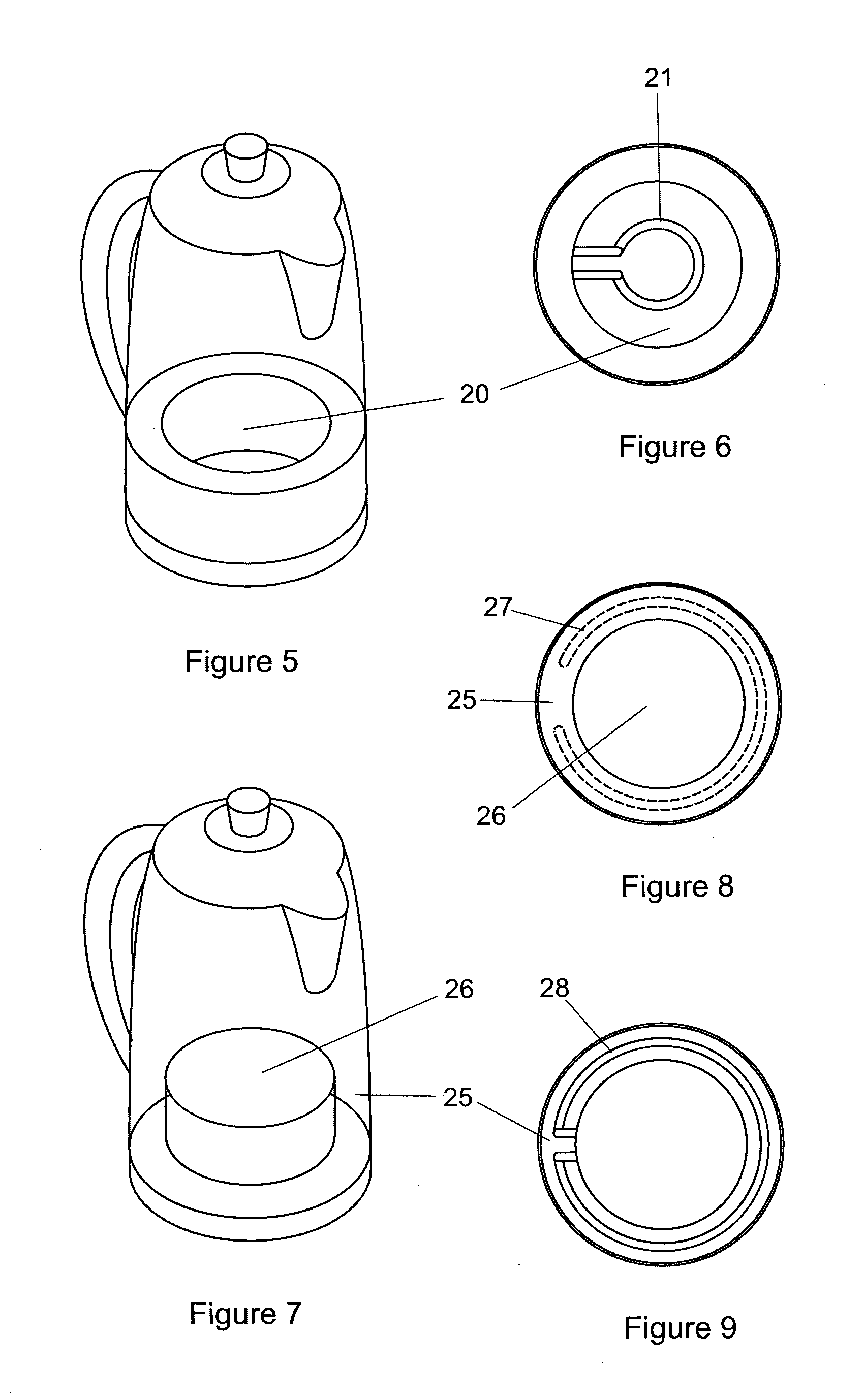
[0032]In practice, the body wall could be made of transparent material such as glass, as is the instance of the embodiment illustrated in FIG. 2, or it could have a window (9) as in the instance illustrated in FIG. 4 through an otherwise opaque body wall. As a further alternative an open topped, generally upright transparent tube communica...


PUM


Abstract

A kettle (1) is provided having a body (2) with a lowermost outer periphery (3), a water chamber (4) inside the body wherein the water chamber has a bottom (5), a lower region (6) immediately above the bottom and a central region (7) that together define a maximum volume of water of at least 1 litre, and typically from 1.4 to 1.8 litres. A transparent wall section or window (9) enables visual observation of the water level. Electrical heating means (11, 21, 27, 28) are provided for heating the water. The lower region of the water chamber has an average horizontal sectional area that is not more than 75%, and preferably not more than 50% of the area enclosed by the lowermost outer periphery. This enables one or 2 cups of water to occupy a greater vertical height in the water chamber and a minimum volume of water of 400 millilitres, and preferably 300 millilitres or less to be visible through the transparent wall section or window. The arrangement greatly facilitates introducing only one or two cups of water into the kettle.

Description

FIELD OF THE INVENTION[0001]This invention relates to an electric kettle or, as it is sometimes referred to, electrically heated jug, whereby small quantities of water of up to about one to two litres can be heated, typically to boiling point, for the purpose of making beverages or utilising the boiling water for any other purpose that may be food preparation or cooking.[0002]It is to be understood that the term “kettle” as used in this specification is intended to include any domestic type of water heating apparatus having a single volume water chamber with electrical heating means at or towards the bottom thereof whereby a variable volume of water can be brought to the boil, or close to the boil, with the variable volume having a maximum of from about 1 litre to about 2 litres and a minimum that is dependent on the configuration of the water chamber and electrical heating means.BACKGROUND TO THE INVENTION[0003]Kettles are frequently used for the purpose of heating water in order t...

Claims


Application Information

Patent Timeline
Patent Type & Authority Applications(United States)
IPC IPC(8): A47J27/21
CPCA47J27/21016A47J2203/00A47J27/21166
Inventor VON SEIDEL, MICHAEL
Owner VON SEIDEL MICHAEL
Why Eureka
Try Eureka