Alignment independent and self-aligning inductive power transfer system

Inactive Publication Date: 2012-06-14
SABO ANTHONY
View PDF8 Cites 251 Cited by
  • Summary
  • Abstract
  • Description
  • Claims
  • Application Information

AI Technical Summary

Benefits of technology

[0010]The unique assembly of the present invention assures that the transfer of inductive power will occur regardless of the orientation of the appliance relative to the charging source. To achieve this result, the source may be config

Problems solved by technology

The drawbacks of such an ar

Method used


Image

  • Alignment independent and self-aligning inductive power transfer system
  • Alignment independent and self-aligning inductive power transfer system
  • Alignment independent and self-aligning inductive power transfer system

Examples


Embodiment Construction

[0021]The invention relates to an induction power transfer device which is operable to charge a cordless battery powered appliance such as a hand tool, laptop computer, music player, or the like. In its broadest sense, the invention is a universal inductive interface power connection system including both a powered “source” and a cordless “receiver” which can be used together to transfer power from the source to a variety of receivers for charging the same.

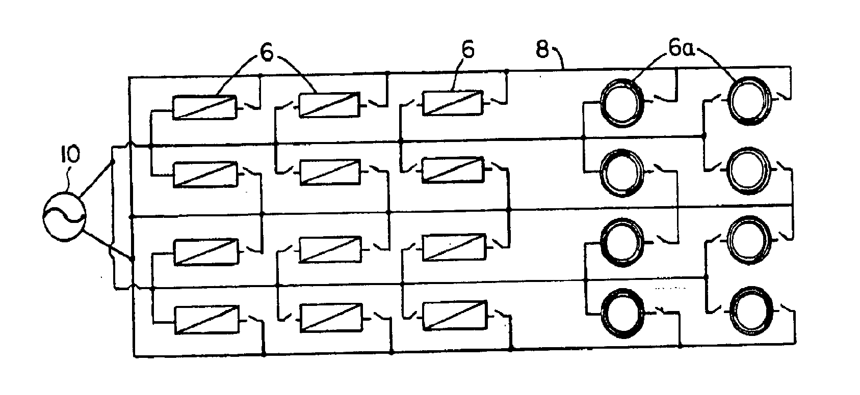
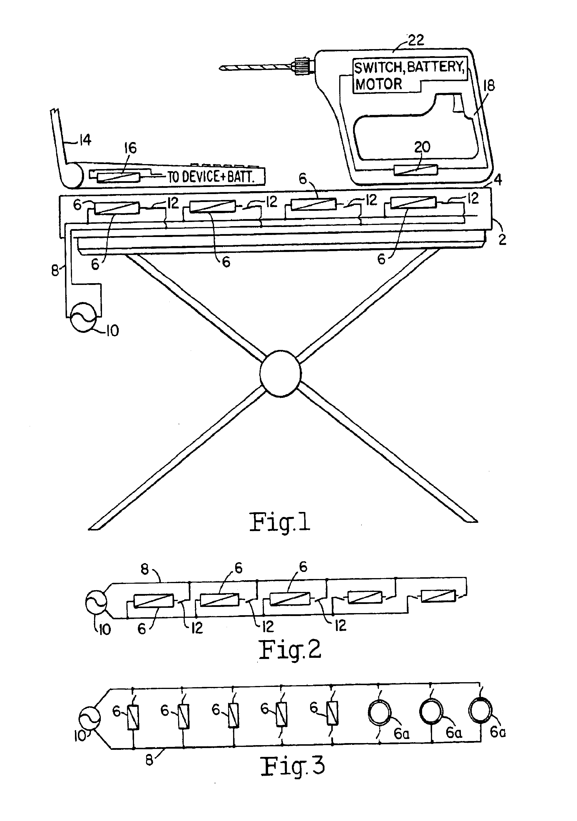
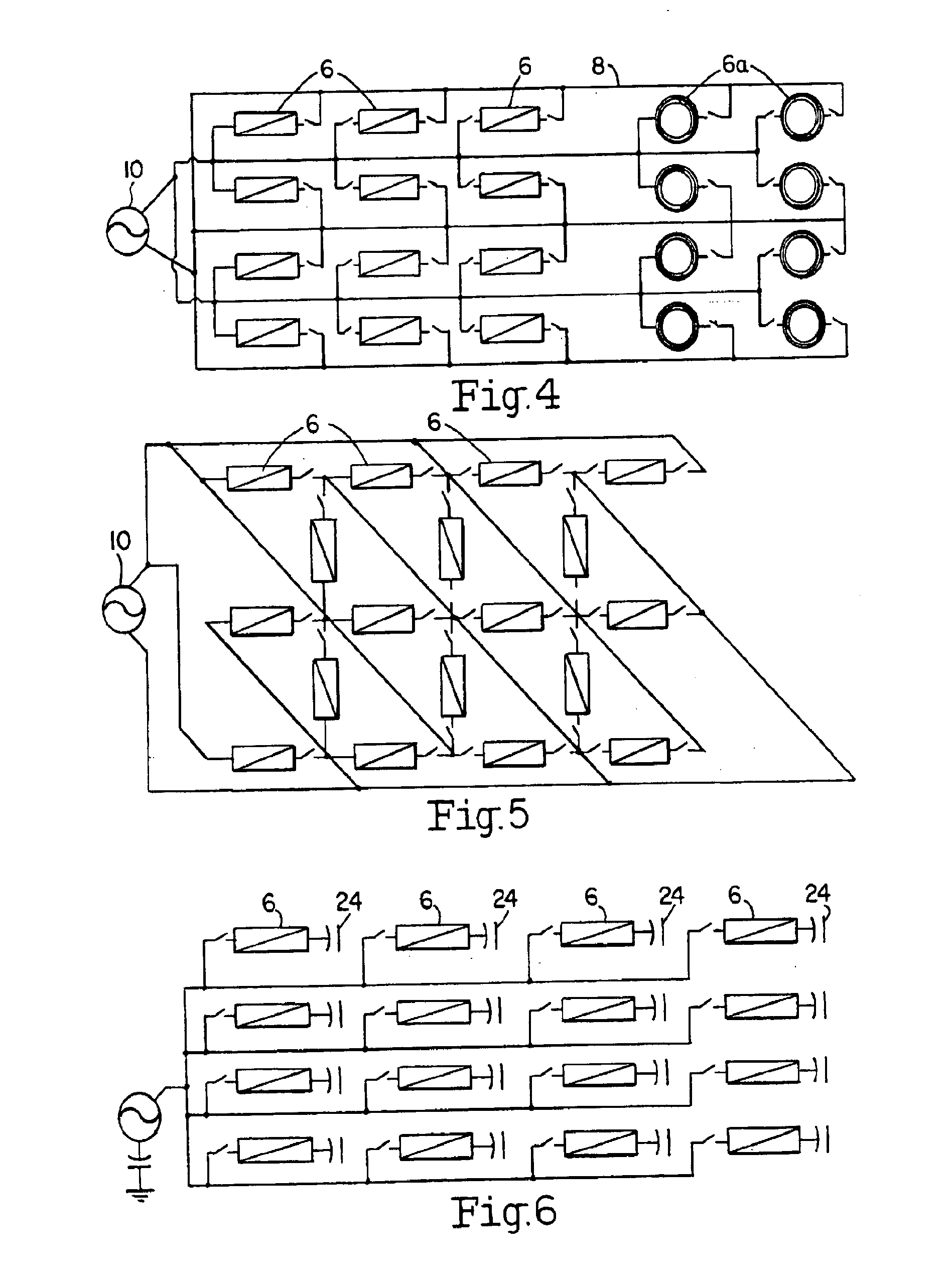
[0022]The induction power transfer device includes a housing which may take one of several forms. In FIG. 1, the housing comprises a bench or table 2 having a flat upper surface 4. Beneath the surface is a planar array of inductors 6 which operate as the primary inductors of one or more transformers. As will be developed below, each inductor comprises a coil having a longitudinal axis. A magnetic core may be provided for each coil.

[0023]The inductors 6 are connected with an electrical conductor 8 which in turn is connected with a ...


PUM


Abstract

An inductive power transfer device is provided for recharging cordless appliances. The device includes a plurality of inductors arranged in an array and connected with a power supply via switches which are selectively operable to activate the respective inductors. The inductors serve as the primary coil of a transformer. The secondary coil of the transformer is arranged in the appliance. When the appliance is arranged proximate to the power transfer device with the respective coils in alignment, power is inductively transferred from the device to the appliance via the transformer.

Description

REFERENCE TO PRIORITY DOCUMENTS[0001]This Application claims priority under 35 USC §120, and is a continuation of U.S. patent application Ser. No. 10 / 960,102, filed in the USPTO on Oct. 8, 2004, which is incorporated by reference for all purposes. Said application Ser. No. 10 / 960,102 is a continuation-in-part, claiming priority under 35 USC §120 to U.S. application Ser. No. 09 / 702,234, filed in the USPTO on Oct. 31, 2001, and issued as U.S. Pat. No. 6,803,744, issued Oct. 12, 2004, which is incorporated by reference for all purposes. U.S. patent application Ser. No. 09 / 702,234 claims priority under 35 USC §119(e) to U.S. Provisional Application Ser. No. 60 / 162,295 filed Nov. 1, 1999, which is incorporated by reference for all purposes.BACKGROUND OF THE INVENTION[0002]The present invention generally relates to inductive power transfer devices for charging or powering cordless appliances.[0003]Currently, cordless electrically operated devices are charged by a source of electrical ener...

Claims


Application Information

Patent Timeline
IPC IPC(8): H01F38/14H02J7/02
CPCH02J7/025H01F38/14H02J50/10H02J7/00302H02J50/12
Inventor SABO, ANTHONY
Owner SABO ANTHONY
Why Eureka
Try Eureka