Switch module and lighting control system comprising the switch module

Active Publication Date: 2012-06-14
NXP BV
View PDF5 Cites 6 Cited by
  • Summary
  • Abstract
  • Description
  • Claims
  • Application Information

AI Technical Summary

Benefits of technology

[0015]In an embodiment switch module may receive a command to make the switch module leave a group. Such a command may involve user selection of a reset button on the switch module for example. The switch module may respond by changing the ID information value in its memory. In a further embodiment this is disabled when

Problems solved by technology

The home network of US2007/205670 has the disadvantage that it requires selection of the multi-way group via a user interface.
This requires overhead costs, and it may make installation to

Method used


Image

  • Switch module and lighting control system comprising the switch module
  • Switch module and lighting control system comprising the switch module
  • Switch module and lighting control system comprising the switch module

Examples


Embodiment Construction

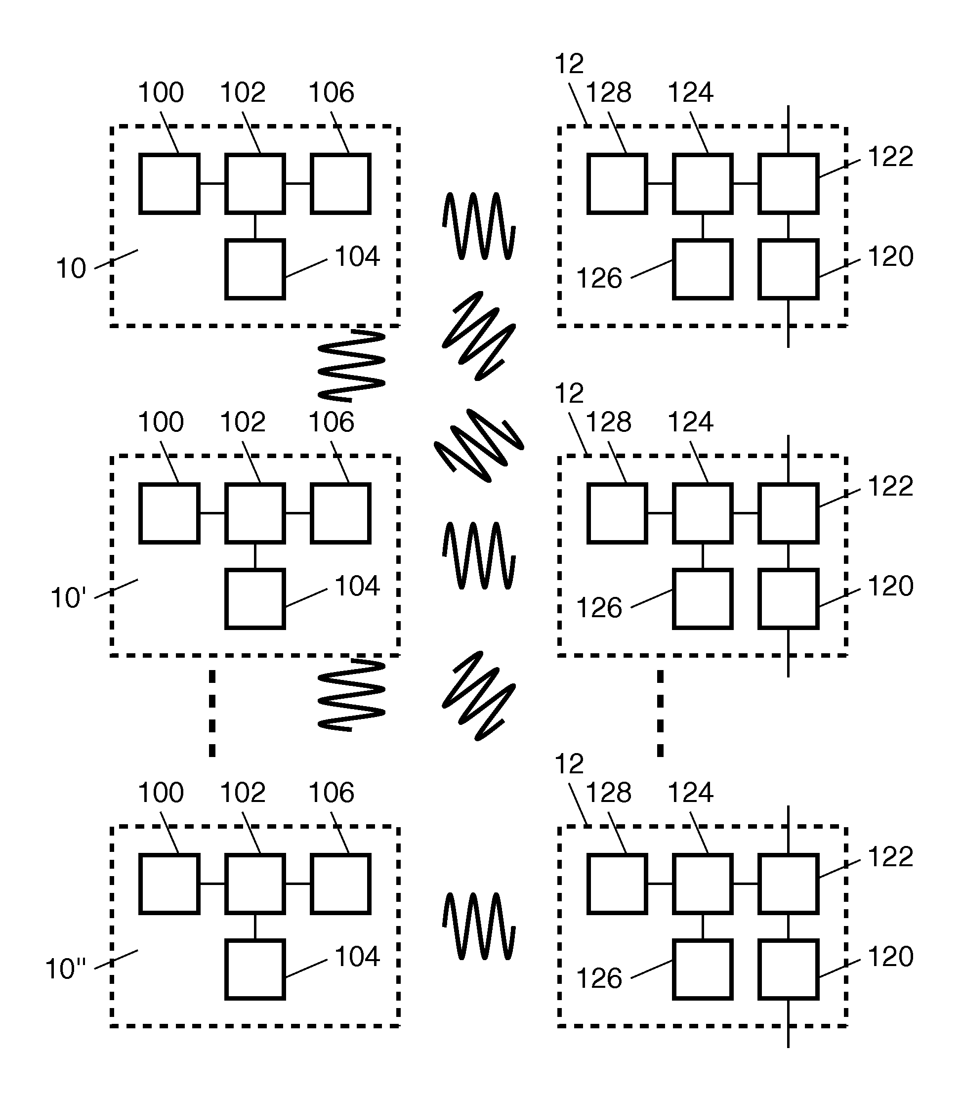
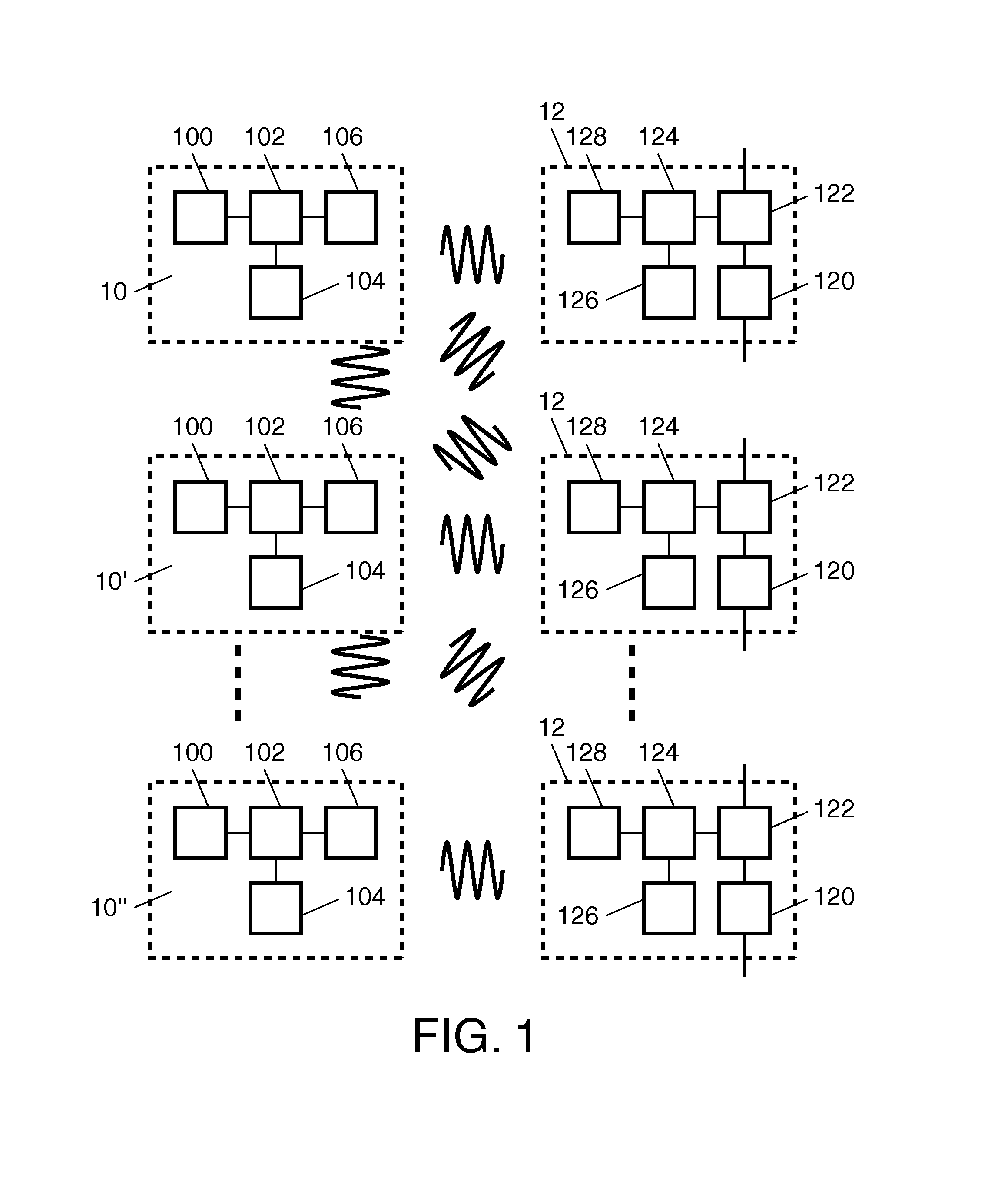
[0019]FIG. 1 shows a lighting control network with a plurality of switch modules 10, 10′, 10″ and lamp units 12. Although three switch modules 10, 10′, 10″ are shown, it should be appreciated that different numbers may be used, also the number of lamp units need not equal the number of switch modules. Each switch module 10, 10′, 10″ is provided with a switch sensor 100 for detecting actuation by a user, a processing circuit 102, a memory 104 and a transceiver 106. Processing circuit 102 is coupled to switch sensor 100, memory 104 and transceiver 106. Processing circuit 102 may comprise a programmable micro-controller and a program memory with a program that configures the micro-controller to perform the functions of processing circuit 102.

[0020]Each lamp unit 12 comprises a light producing device 120, a current control device 122, a processing circuit 124, a memory 126 and a receiver 128. Transceiver 106 and receiver 128 may be configured to transmit wireless messages (e.g. messages...


PUM


Abstract

A switch module is designed to facilitate user definition of a group of switch modules that control the same lamp. A lamp unit (12) containing the lamp responds selectively to messages from the switch modules (10, 10′) when the messages comprise ID information matching with ID information stored in the lamp unit (12). A group is formed by detecting user control operation of sensors (100) in the switch modules (10, 10′), transmitting messages from the switch modules (10, 10′) in response and determining from the messages whether the switch modules (10′) have both been operated within a time interval with a duration of less than a predetermined threshold. If so, the ID information value in memories (104) of the switch module (10) and/or the further switch module (10′) are set to matching ID values, for use in the messages to control the lamp unit.

Description

FIELD OF THE INVENTION[0001]The invention relates to a switch module for use in a lighting control system, a lighting control system comprising such a switch module and a method of operating a lighting control system.BACKGROUND OF THE INVENTION[0002]US patent application No. 2007 / 205670 describes the use of a home network to control lamps and other devices in the home. The use of a multi-way switch group is described, with a plurality of switches that are used to control the same lamp. A user interface is provided that has a display on which the user can select the switches that will be part of the multi-way switch group. Based on this selection, a multi-way message packet is transmitted to inform the switches of the membership of the multi-way switch group. Upon reception of such a message packet the relevant switches copy the setting state specified by the message packet.[0003]The home network of US2007 / 205670 has the disadvantage that it requires selection of the multi-way group ...

Claims


Application Information

Patent Timeline
IPC IPC(8): H04B1/38
CPCG08C17/02H04L12/282H05B39/088H05B37/0272H04L2012/2841H05B47/19H05B47/195
Inventor KOPPELAAR, ARIE GEERT CORNELISMOONEN, OSWALDFRIMOUT, EMMANUEL DAVID LUCAS MICHAELBRANDSMA, EWOUTKOOLEN, GERT-JAN
Owner NXP BV
Why Eureka
Try Eureka