
Pulse radar receiver

a radar receiver and pulse technology, applied in the field of pulse radar receivers, can solve the problems of range gating scheme limitation, high resolution implementation limitation of conventional pulse radar receivers, and limited range resolution of range gating schemes, so as to achieve high distance resolution

Inactive Publication Date: 2012-06-14
ELECTRONICS & TELECOMM RES INST
View PDF11 Cites 11 Cited by
  • Summary
  • Abstract
  • Description
  • Claims
  • Application Information

AI Technical Summary

Benefits of technology

[0009]Embodiments of the present invention are directed to a pulse radar receiver that provides a high distance resolution by generating a sampling frequency with a difference from a TX pulse to sample a reflected wave received through an RX antenna.

Problems solved by technology

Therefore, the conventional pulse radar receiver has a limitation in implementing a high resolution because a distance resolution is determined by a pulse width.
In such a scheme, the receiving scheme may have a high signal-to-noise ratio (SNR) in an RX pulse, but still there is a limitation in implementing a high resolution.
However, the range gating scheme has a limitation in increasing the resolution of a range determined by a pulse width.

Method used


Image

  • Pulse radar receiver
  • Pulse radar receiver
  • Pulse radar receiver

Examples


Embodiment Construction

[0017]Hereinafter, a pulse radar receiver in accordance with the present invention will be described in detail with reference to the accompanying drawings. Herein, the drawings may be exaggerated in thicknesses of lines or sizes of components for the sake of convenience and clarity in description. Furthermore, terms used herein are defined in consideration of functions in the present invention and may be varied according to the custom or intention of users of operators. Thus, definition of such terms should be determined according to overall disclosures set forth herein.

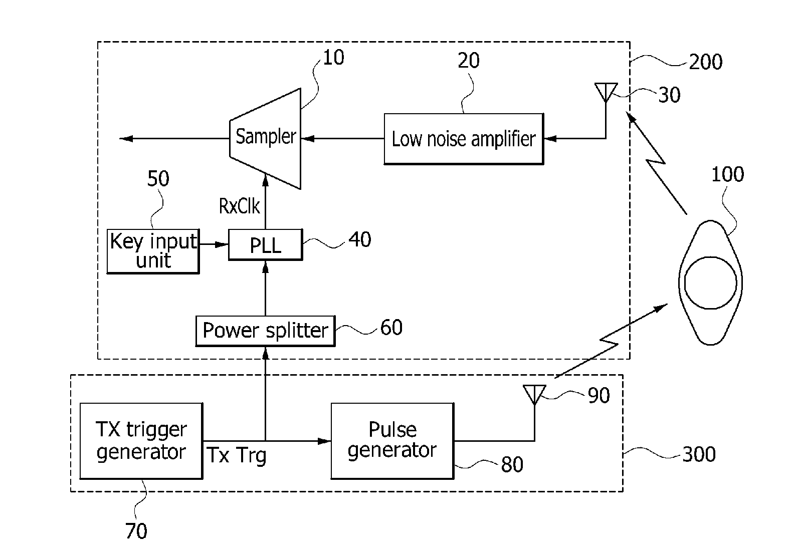
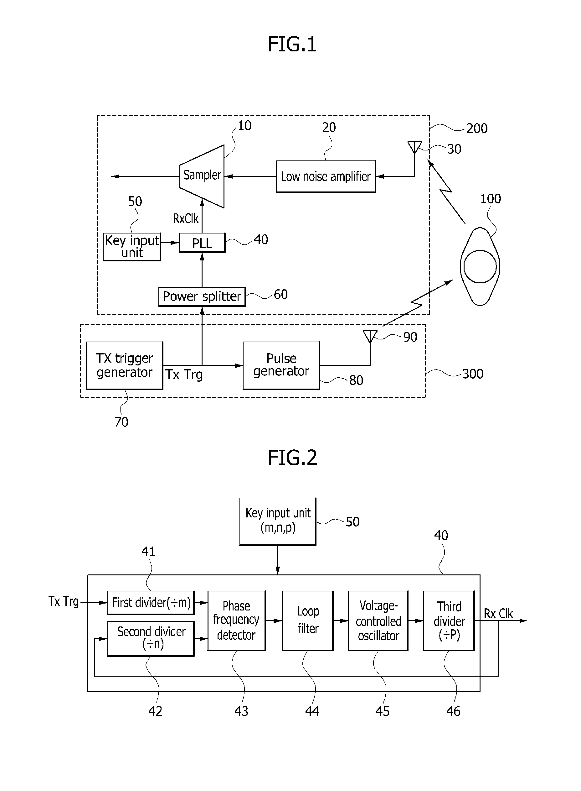
[0018]FIG. 1 is a block diagram of a pulse radar receiver according to an embodiment of the present invention. FIG. 2 is a block diagram of a phase-locked loop (PLL) of a pulse radar receiver according to an embodiment of the present invention.

[0019]As illustrated in FIG. 1, a pulse radar receiver according to an embodiment of the present invention includes a power splitter 60, a phase-locked loop (PLL) 40, and a sam...


PUM


Abstract

A pulse radar receiver includes a power splitter configured to split a transmit (TX) trigger signal for generating a TX pulse, a phase-locked loop (PLL) configured to receive a division ratio and the TX trigger signal split by the power splitter, and generate a sampling frequency, and a sampler configured to sample a reflected wave received through an RX antenna, according to the sampling frequency generated by the PLL. Accordingly, it is possible to provide a high distance resolution by generating a sampling frequency with a difference from a TX pulse to sample a reflected wave received through an RX antenna. Thus, it is possible to overcome a limitation in the distance resolution due to the pulse width and to measure a minute movement at a short distance. Therefore, the pulse radar receiver is applicable to high range resolution radar applications such as a living body measuring radar.

Description

CROSS-REFERENCE TO RELATED APPLICATIONS[0001]The present application claims priority to Korean patent application number 10-2010-0125810, filed on Dec. 9, 2010, which is incorporated by reference in its entirety.BACKGROUND OF THE INVENTION[0002]The present invention relates to a pulse radar receiver, and more particularly, to a pulse radar receiver that provides a high distance resolution by using a receive (ΔX) sampling frequency that has an adjustable offset frequency (Δf) from a transmit (TX) pulse repetition frequency (PRF) to sample a reflected wave received through a receive (RX) antenna.[0003]In general, a radar (radio detection and ranging) is a sensor that detects the presence of an object beyond the limitations of a human visual range. A pulse radar includes a radar transmitter and a radar receiver. The radar transmitter transmits a TX pulse by at TX pulse repetition periods, and the radar receiver receives an echo signal of the TX pulse reflected from a target, thereby ac...

Claims


Application Information

Patent Timeline
IPC IPC(8): G01S7/285
CPCG01S7/292
Inventor PARK, PIL JAEKIM, SEONG DOWOO, SUNG CHULYU, HYUN KYU
Owner ELECTRONICS & TELECOMM RES INST
Learn More