Display device and multilayer substrate

a multi-layer substrate and display device technology, applied in the field of display devices and multi-layer substrates, can solve the problems of reducing display contrast ratio, and affecting the contrast ratio of display, so as to inhibit reflection and high contrast ratio

Active Publication Date: 2012-06-14
SHARP KK
View PDF2 Cites 39 Cited by
  • Summary
  • Abstract
  • Description
  • Claims
  • Application Information

AI Technical Summary

Benefits of technology

[0069]The present invention makes it possible to obtain a display device having a high contrast ratio even in an environment with bright surrounding area. Furt

Problems solved by technology

Light leak occurring during black display is generally known as the reason for decreased contrast ratio of display, but the decrease in contrast ratio of display has been found to be greatly affected by reflection based on the display device structure.
Such reflected light is the cause for decreased contrast ratio of display.
Light leak occurring when black color is displayed can be considered as a cause for reduced contrast ratio of display.
In such a case, the image displayed on the display screen of the

Method used


Image

  • Display device and multilayer substrate
  • Display device and multilayer substrate
  • Display device and multilayer substrate

Examples


embodiment 1

[0109]Embodiment 1 relates to a multilayer substrate that can be used as a color filter substrate in a liquid crystal display device. The multilayer substrate according to Embodiment 1 is the second multilayer substrate of the present invention. The multilayer substrate according to Embodiment 1 has a polarizer, a glass substrate (transparent substrate), a moth eye film, a color filter layer, a black matrix (BM), and a common electrode.

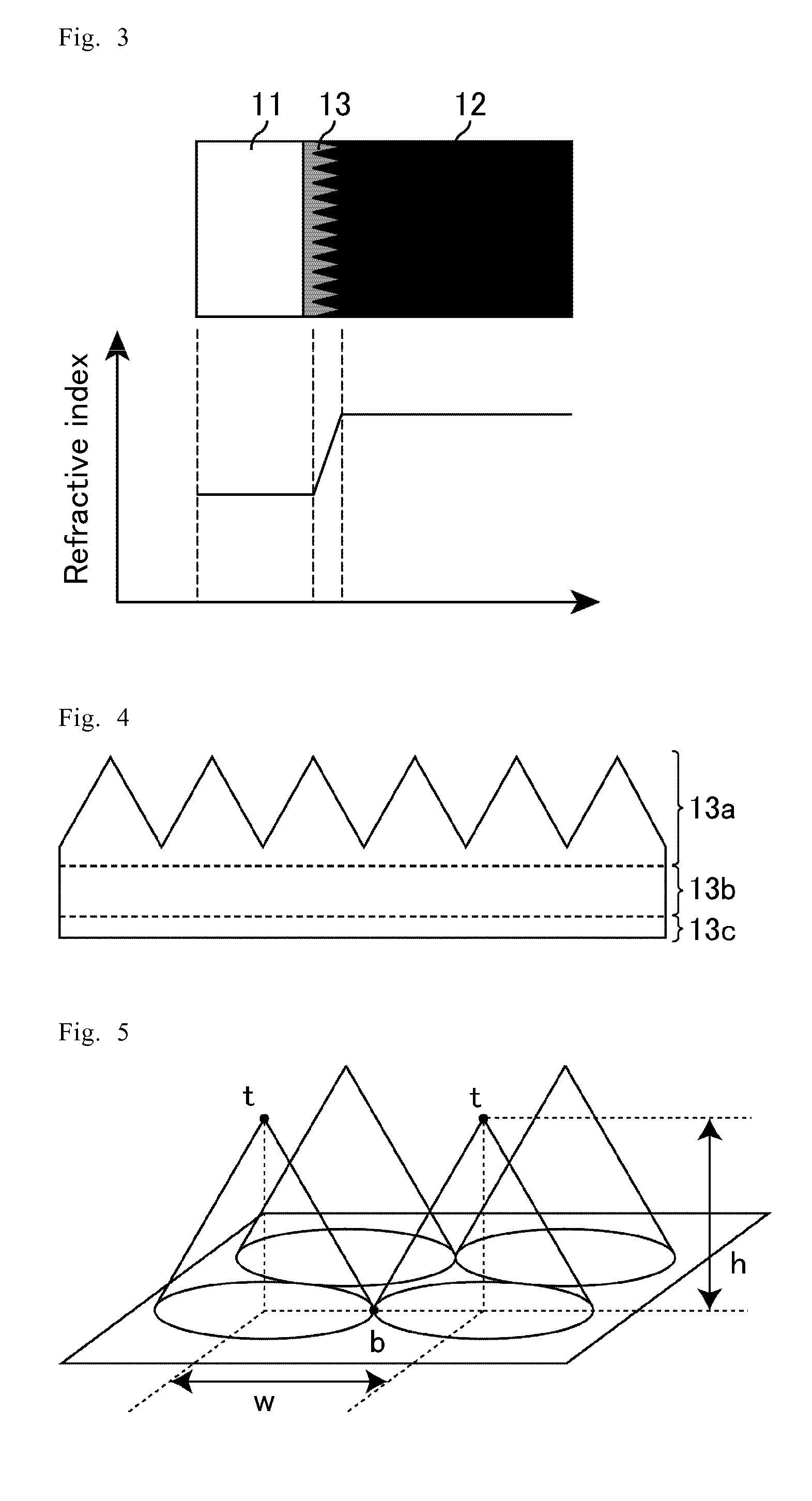
[0110]FIG. 3 is a schematic diagram in which portions of glass substrate, moth eye film, and black matrix of the multilayer substrate of Embodiment 1 are extracted. This figure shows the arrangement configuration of the glass substrate, moth eye film, and black matrix and refractive index distribution thereof. In Embodiment 1, a moth eye film 13 corresponds to the fourth layer of the present invention, and a BM 12 corresponds to the fifth layer of the present invention.

[0111]The moth eye film 13 is constituted by an acrylic UV resin (for example, uret...

embodiment 2

[0138]Embodiment 2 relates to a multilayer substrate that can be used as a color filter substrate in a liquid crystal display device. The multilayer substrate of Embodiment 2 is the first multilayer substrate of the present invention. The multilayer substrate of Embodiment 2 is provided with a polarizer, a glass substrate, a color filter layer, a black matrix, and a common electrode.

[0139]FIG. 20 is a schematic diagram in which a portion of the glass substrate and black matrix of the multilayer substrate of Embodiment 2 is extracted; this figure shows the arrangement configuration of the glass substrate and black matrix and the refractive index distribution thereof. In Embodiment 2, the glass substrate (transparent substrate) 11 corresponds to the first layer of the present invention, and the BM 12 corresponds to the second layer of the present invention. The BM 12 includes carbon black particles 31 demonstrating black color of the BM 12 and a binder resin (medium) 32 enclosing the ...

embodiment 3

[0144]Embodiment 3 relates to a multilayer substrate that can be used as a color filter substrate in a liquid crystal display device. The multilayer substrate of Embodiment 3 is the second multilayer substrate of the present invention. The multilayer substrate of Embodiment 3 is provided, with a polarizer, a moth eye film, an intermediate layer, a glass filter, a black matrix (BM), and a common electrode.

[0145]FIG. 21 is a schematic diagram in which, a portion of the glass substrate, moth eye film, intermediate resin layer, and black matrix of the multilayer substrate of Embodiment 3 is extracted; this figure shows the arrangement configuration of the glass substrate, moth eye film, intermediate resin layer, and black matrix and the refractive index distribution thereof. In Embodiment 3, the moth eye film 13 corresponds to the fourth layer of the present invention, and the intermediate resin layer 14 corresponds to the fifth layer. The moth eye film 13 is constituted, for example, b...


PUM

PropertyMeasurementUnit
Reflectanceaaaaaaaaaa
Wavelengthaaaaaaaaaa

Abstract

A display device is provided in which reduction of reflected light is realized. Also a multilayer substrate is provided in which light reflectance is reduced even when the substrate has a plurality of layers that differ in refractive index from each other. In the display device of one embodiment, the reflectance of light reflected by the internal structure, of light incident on the internal structure through a display screen, is less than 1.0%. The multilayer substrate of one embodiment includes a first layer and a second layer disposed adjacently to the first layer. The refractive index of the second layer varies continuously from an interface where the second layer is adjacent to the first layer in a direction from the first layer, with the variation being started at a value of the refractive index at the interface where the first layer is adjacent to the second layer.

Description

TECHNICAL FIELD[0001]The present invention relates to a display device and a multilayer substrate.BACKGROUND ART[0002]Display devices provided in electronic devices such, as television sets, personal computers, cellular phones, and digital cameras that have been used in very large numbers in recent years are usually fabricated by using a substrate from glass or the like as a base, and a display device is produced by disposing circuit elements, control elements, and color filters on this substrate.[0003]For example, a liquid crystal display device is provided with a transparent substrate such as glass and color filters formed on the transparent substrate. By providing the color filters, it is possible to colorize the display light. Therefore, a liquid crystal display device provided with color filters can display color images. The transparent substrate is disposed on the display surface side and color filters are disposed on the inner surface side of the liquid crystal display device...

Claims


Application Information

Patent Timeline
IPC IPC(8): G02F1/1333B32B7/02F21V7/00
CPCG02B1/11G02B1/118G02B5/201G02F1/133512Y10T428/24942B29D11/00326G02F1/133502G02F2202/36G02F2202/40G02F2201/38
Inventor YAMADA, NOBUAKISAKURAGI, KAZUYOSHIFUJII, AKIYOSHITAGUCHI, TOKIO
Owner SHARP KK
Why Eureka
Try Eureka