Access point terminal, wireless communication terminal, wireless communication system, wireless communication method, program and integrated circuit

a wireless communication terminal and access point technology, applied in the field of information processing techniques, can solve the problems of user inability to execute a service smoothly, radio wave interference frequently occurring, and overflowing of the 5 ghz band, and achieve the effect of less radio wave interference and high real-timeliness in wireless communication

Inactive Publication Date: 2012-06-14
PANASONIC INTELLECTUAL PROPERTY MANAGEMENT CO LTD
View PDF8 Cites 38 Cited by
  • Summary
  • Abstract
  • Description
  • Claims
  • Application Information

AI Technical Summary

Benefits of technology

[0031]The present invention enables, for example, to (i) focus on a wireless communication terminal which executes an application requiring high real-timeliness in wireless communication, and (ii) allocate a first frequency band with less radio wave interference (for example, the 5 GHz band) to the wireless communication terminal, thereby provide a wireless LAN environment appropriate for the usage of the wireless communication terminal.

Problems solved by technology

However, as the number of wireless LAN devices increases, there are cases where a user cannot execute a service smoothly because a band available for a wireless LAN device is overwhelmed.
Furthermore, in a 2.4 GHz band, there is a problem that radio wave interference frequently occurs when the band is used by various devices, because the 2.4 GHz band is an Industry Science Medical (ISM) band.
However, if all terminals are connected through the 5 GHz band as there is less interference, the 5 GHz band becomes overwhelmed, which is like putting the cart before the horse.
However, with the effective usage of wireless LAN band in the line acquisition method having the configuration described above, the communication traffic volume per se is restricted equally for all of the terminals.
Therefore, a band is unnecessarily allocated to a terminal which is not requiring a band, which makes it impossible to properly allocate a band for a terminal which is requiring a band.
Furthermore, restricting a communication traffic volume is not always effective, since in general a wireless band cannot be quantitatively manipulated.

Method used


Image

  • Access point terminal, wireless communication terminal, wireless communication system, wireless communication method, program and integrated circuit
  • Access point terminal, wireless communication terminal, wireless communication system, wireless communication method, program and integrated circuit
  • Access point terminal, wireless communication terminal, wireless communication system, wireless communication method, program and integrated circuit

Examples


first embodiment

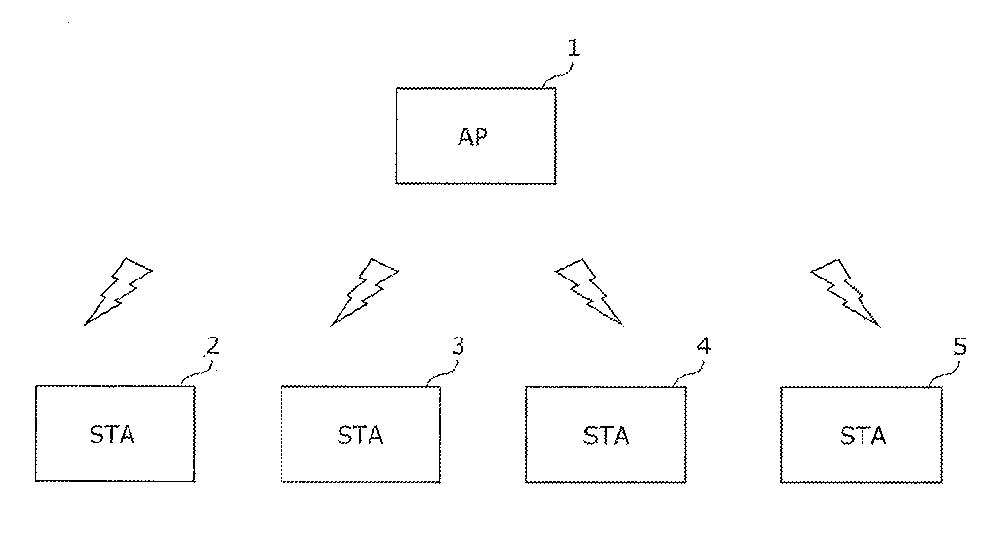
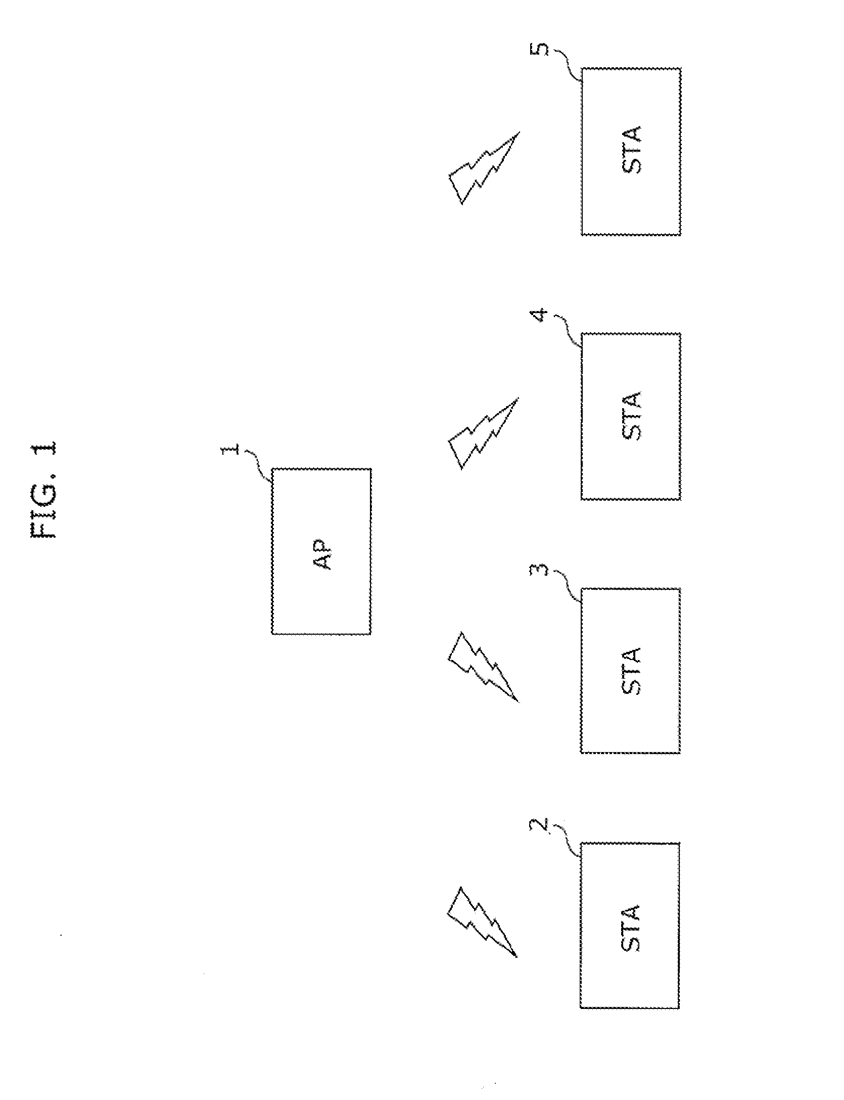
[0063]First, a configuration diagram of a wireless LAN system according to a first embodiment is described. The wireless LAN system according to the first embodiment includes an access point terminal 1 (hereinafter referred to as AP) and wireless communication terminals 2 to 5 (hereinafter referred to as STA). The STA2 to the STA5 are connected using an infrastructure mode and communicate under a control of the AP1. The number of the STAs is 4 in the first embodiment, however, it goes without saying that it is not limited to the number.

[0064]Furthermore, the STA2 to the STA5 are connected with the AP1 using Wi-Fi Protected Setup (WPS), which is an easy setup for wireless LAN advocated by Wi-Fi Alliance (WFA). It goes without saying that, without being limited to WPS, other easy connections for wireless LAN may be used, such as the easy connection which (i) enables an automatic key exchange between the AP1 and each of the STA2 to the STA5, and (ii) allows the AP1 to distribute connec...

second embodiment

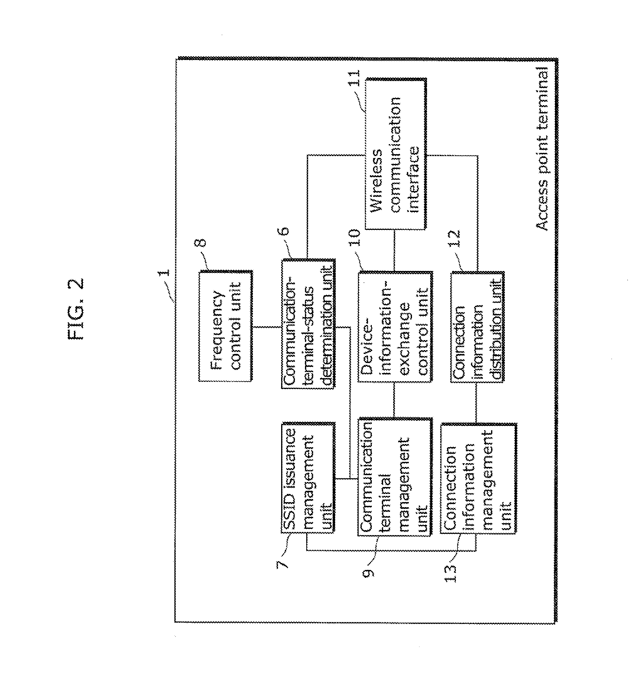
[0149]Next, the second embodiment is described. The difference between the first embodiment and the second embodiment is in the way the AP1 assigns the SSID. Specifically, it is different that, in the first embodiment, the SSID issuance control unit 7 assigns the unique SSID to each of the STA2 to the STA5, while, in the second embodiment, the SSID issuance control unit 7 assigns a unique SSID to each of the categories to which each of the STA2 to the STA5 belongs. The description on commonalities with the first embodiment is omitted in the description below to focus on differences.

[0150]The AP1 starts the WPS and so forth with the STA2 (S101), and obtains the device information of the STA2 (S102), in the same manner as the first embodiment. The device information includes, for example, the uuid, the Primary Device Type, or the Category which are assigned uniquely to each of the STA2 to the STA5.

[0151]For example, as examples of the Primary Device Type, “Television”, “PVR”, and “PC”...

third embodiment

[0169]The difference between the third embodiment and the first embodiment is in a specific procedure of determining whether or not the STA2, the STA3 and the STA5 has executed the application requiring real-timeliness. Specifically, it is different that the communication-terminal-status determination unit 6 determines, in the first embodiment, based on whether or not the volume of the wireless communication is greater than the threshold, while, in the second embodiment, based on whether or not priority of communication data is greater than the threshold. It is to be noted that to perform communication with priority of communication data greater than the threshold is an example of the communication status to satisfy the predetermined condition. The description on commonalities with the first embodiment is omitted in the description below to focus on differences.

[0170]In the third embodiment, a specific process is described in detail, where the process is for determining, by the comm...


PUM


Abstract

An access point terminal includes: a communication-terminal-status determination unit which determines a communication status of one wireless communication terminal out of wireless communication terminals, by obtaining a wireless signal transmitted or received by the one wireless communication terminal; and a frequency control unit which uses (i) a first frequency band for wireless communication with the one wireless communication terminal and (ii) a frequency band other than the first frequency band for the wireless communication with one or more of the wireless communication terminals other than the one wireless communication terminal, when the communication-terminal-status determination unit determines that the communication status of the one wireless communication terminal satisfies a predetermined condition.

Description

CROSS REFERENCE TO RELATED APPLICATION(S)[0001]This is a continuation application of PCT Patent Application No. PCT / JP2011 / 003531 filed on Jun. 21, 2011, designating the United States of America, which is based on and claims priority of Japanese Patent Application No. 2010-141045 filed on Jun. 21, 2010. The entire disclosures of the above-identified applications, including the specifications, drawings and claims are incorporated herein by reference in their entirety.BACKGROUND OF THE INVENTION[0002](1) Field of the Invention[0003]The present invention relates to information processing techniques, and particularly to an information processing technique that enables efficient use of a band in wireless communication.[0004](2) Description of the Related Art[0005]In recent years, many devices which can be used with wireless LANs are commercialized and it is possible to use various applications with ease and convenience. Furthermore, it is known that the advent of Institute of Electrical ...

Claims


Application Information

Patent Timeline
Patent Type & Authority Applications(United States)
IPC IPC(8): H04W24/00H04W72/04H04J1/00H04L12/26
CPCH04W72/02H04W72/0453H04W88/08H04W72/048H04W48/08H04W72/0406H04W72/085H04W72/51H04W72/542H04W72/20
Inventor ARASHIN, NOBUHIKOTANAKA, OSAMUYAMADA, TOYOSHINAGOSHI, MASAHIKOSHIOTSUKI, AKIHIKOYAMASAKI, AKIRA
Owner PANASONIC INTELLECTUAL PROPERTY MANAGEMENT CO LTD
Why Eureka
Try Eureka