
Orthodontic aligner fabrication by overlay method

Active Publication Date: 2012-06-14
DENTSPLY SIRONA INC
View PDF4 Cites 79 Cited by
  • Summary
  • Abstract
  • Description
  • Claims
  • Application Information

AI Technical Summary

Benefits of technology

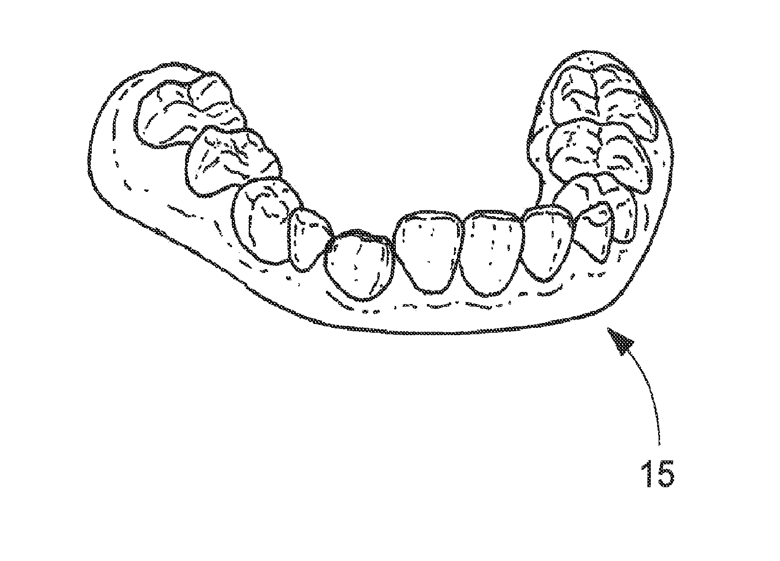
[0009]According to the invention, an alignment tray is fabricated based upon a model that is a physical overlay of both the initial misalignment (or an intermediate one) and a target or final position of the teeth where they are ultimately desired to be moved. The model can be a physical model, a digital model or both. A tray fabricated from such an overlay model will have a force bump or appliance of some kind that is placed into the tray to exert a selected force upon selected teeth to cause them to move as desired. The tray therefore, is itself an overlay that includes both the starting point of the te

Problems solved by technology

As the teeth are moved in such conventional procedures, they will often be blocked by other teeth.
The results of excessive stripping are often not aesthetically appealing or even healthy for the stripped teeth.
While the conventional procedures will move teeth, they do not permit the teeth to move in their more natural or open pathways.
Heretofore, conventional orthodontic aligner trays have not allowed for this type of natural tooth movement in orthodontic procedures.

Method used


Image

  • Orthodontic aligner fabrication by overlay method
  • Orthodontic aligner fabrication by overlay method
  • Orthodontic aligner fabrication by overlay method

Examples


Embodiment Construction

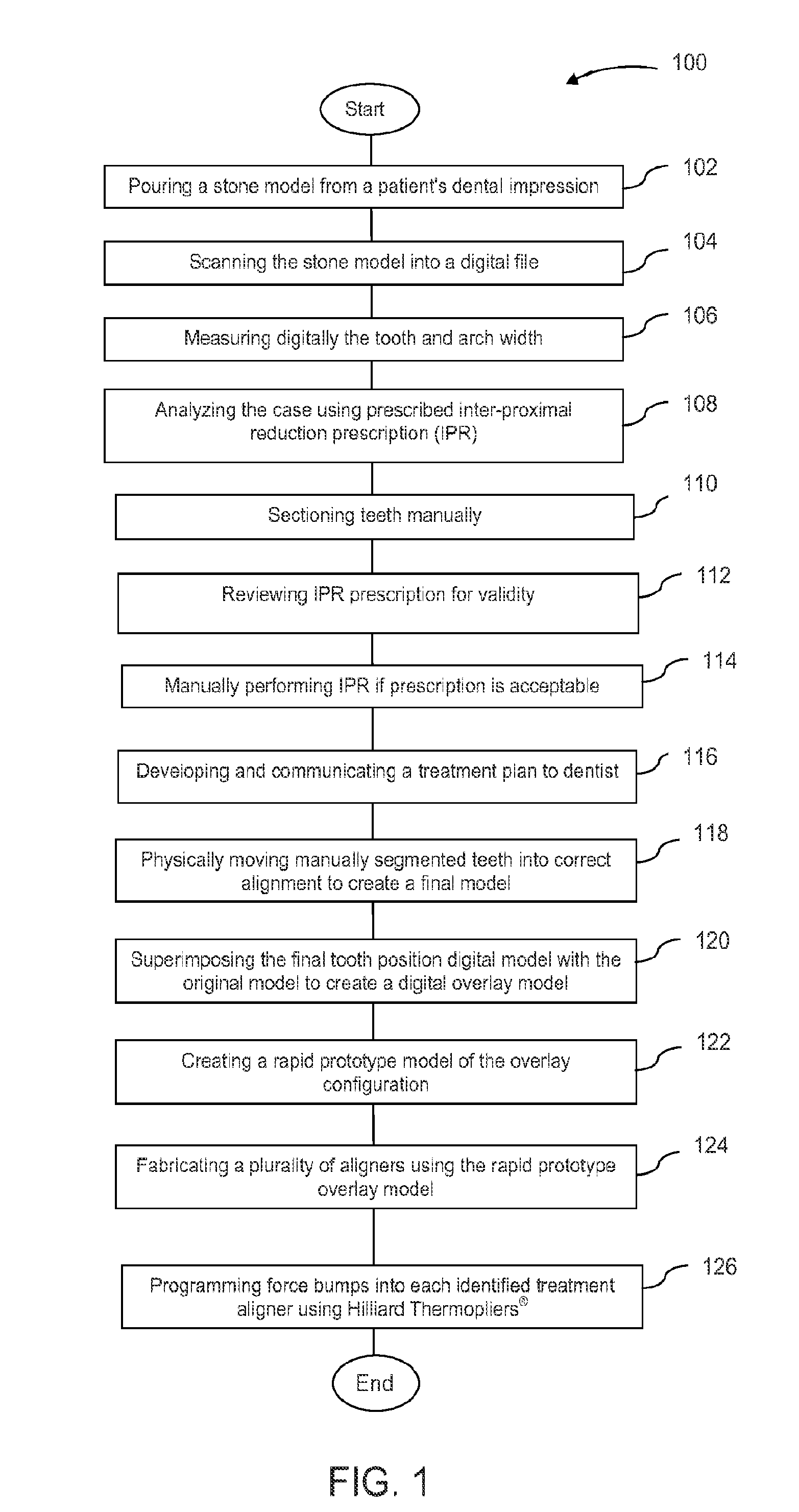
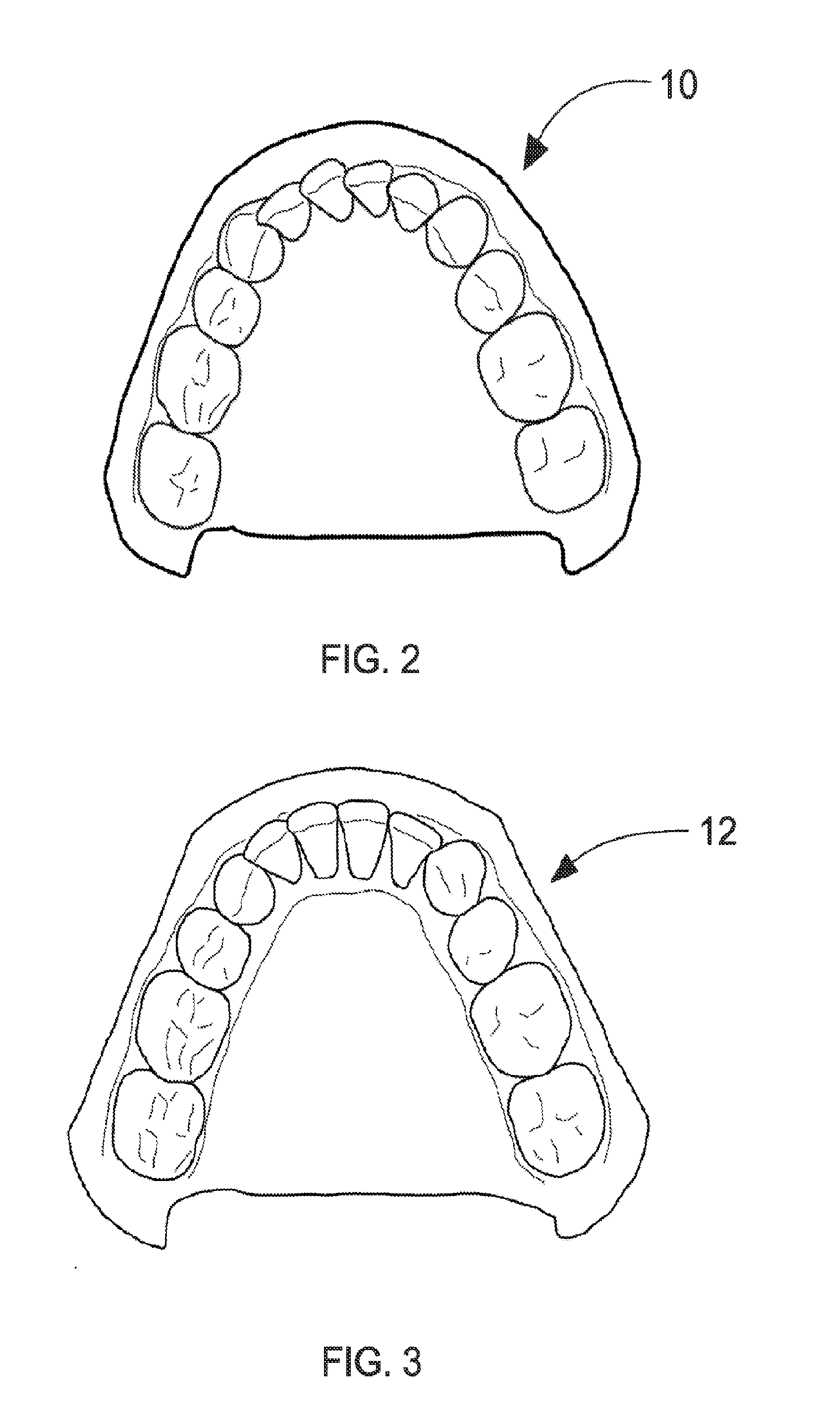
[0030]A method according to the present invention includes several steps. Not all of the following steps are necessary and there are alternatives. For example, although the invention will be characterized as employing, for example, a digital dental model and software to create the inventive models and aligners, it will be appreciated that the procedures can be accomplished manually. Similarly, fabrication methods of physically creating the various inventive components can be by conventional rapid prototyping procedures or the like as will be discussed, again with the understanding that other fabrication techniques can be employed within the scope of the invention.

[0031]The inventive method employing the inventive components therefore, preferably includes receiving, obtaining or otherwise preparing a stone or plaster model of the patient's dentition or even a conventional dental impression thereof. While it is possible that the invention can be carried out by a dental professional, t...


PUM


Abstract

The orthodontic alignment of misaligned teeth includes preparing a digital and / or physical overlay model which is the superimposed positioning of the patient's original misaligned dentition with the target or final position. The superimposition of one upon the other creates an open space through which teeth may move in a natural manner, allowing for a treatment plan that takes into account the physical interaction of one tooth with another or the differences in tooth movement rates due in part to differences in underlying bone density or the like. An aligner tray fabricated using the model will likewise represent the before and after tooth positions and will also have the open space to allow tooth movement. Force exerting structures are preferably placed into the aligner tray to impinge upon the patient's teeth in a prescribed manner when the aligner tray is inserted into the patient's oral cavity.

Description

CROSS-REFERENCE TO RELATED APPLICATIONS[0001]This application claims the benefit of U.S. Provisional Application No. 61 / 274,821 filed Aug. 21, 2009, entitled “ORTHODONTIC ALIGNER AND METHOD”; and U.S. Provisional Patent Application No. 61 / 307,668 filed Feb. 24, 2010 entitled “ORTHODONTIC ALIGNER FABRICATION BY OVERLAY METHOD”. The disclosures of the Provisional Applications are hereby incorporated by reference.TECHNICAL FIELD[0002]The present invention generally relates to the field of orthodontics. More particularly, the invention relates to an orthodontic alignment tray and a method for fabricating such a tray and aligning teeth using manual or digital programming techniques.BACKGROUND OF THE INVENTION[0003]The field of orthodontics is well developed. Using conventional brackets, wires and the like, and based upon the nature of a patient's misaligned teeth, a dental professional can determine a pathway for applying appropriate forces to move teeth into better alignment. As the tee...

Claims


Application Information

Patent Timeline
IPC IPC(8): G06F17/50
CPCA61C7/08A61C7/002A61C9/00
Inventor ANDERSON, MICHAEL C.CLATT, BRADFORD H.HILLIARD, JACK K.
Owner DENTSPLY SIRONA INC
Learn More