Cool vest

a technology of cool vests and hoodies, applied in the field of medical devices, can solve the problems of no reference provided, and achieve the effects of reducing body temperature to hypothermia, preventing and/or limiting further trauma to the heart, brain and/or body, and being easy to fasten

Inactive Publication Date: 2012-06-21
TERRY DENNIS T
View PDF6 Cites 6 Cited by
  • Summary
  • Abstract
  • Description
  • Claims
  • Application Information

AI Technical Summary

Benefits of technology

[0016]This being the case, another object of this invention is to have it portable to quickly apply this cooling therapy at the scene as well as while transporting a patient of an accident or ill patient, thus saving valuable time, which will limit further trauma to the head and / or body.
[0018]The cool vest system according to this invention includes a device that can be worn on the head and body during a traumatic health situation that will lower the body temperature to hypothermia thus preventing and / or limiting further trauma to the heart, brain and / or other vital organs. It is a sleeveless head and body thermal insulated garment that is easily fastened with Velcro adhesive that can be adjusted to accommodate different sized humans. It includes a rubber tube closed circuit coil system filled with water or other liquids that will be cooled via an exterior copper-tubing coil submersed in an ice filled cooler and circulated throughout the coiled system via a pump. While circulating cooled liquids around the head and body it will prevent and / or limit the traumatic damage done to vital organs. This pump will be a part of the closed circuit coil system that can be powered via AC, DC or solar power.

Problems solved by technology

However, none of the references provided has a vest that cools the head and body simultaneously via coil filled with water or other liquid and is portable with a pump.

Method used


Image

  • Cool vest
  • Cool vest
  • Cool vest

Examples


Embodiment Construction

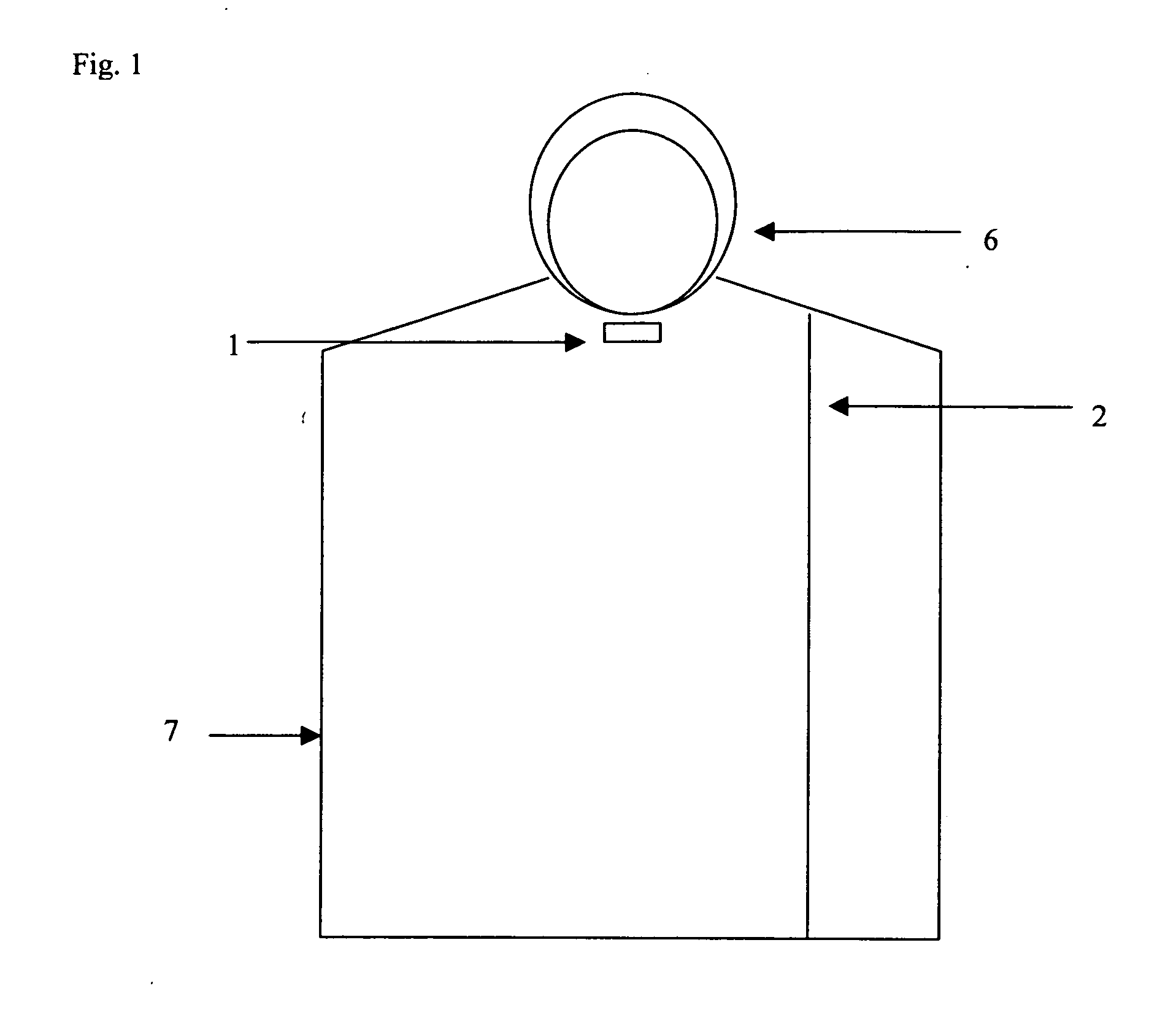
[0047]Referring to FIG. 1, the outer part of the cool vest will be made of thermal insulated cloth 7 covering the head and body to enable the vest to maintain the desired temperature and a facial opening 6. There will at least be two Velcro adhesive fasteners, one for the head 1 and the other for the body 2 and both may be adjusted to accommodate the size of the patient.

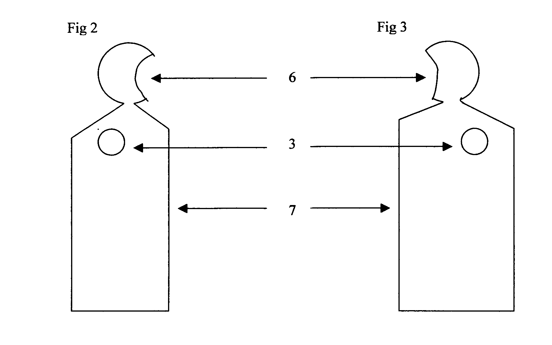
[0048]Referring to FIG. 2, shows the cool vest from the outer right side with an arm opening 3 for easy access as well as an opening for the face 6 and thermal insulated cloth 7.

[0049]Referring to FIG. 3, shows the cool vest from the outer left side with an arm opening 3 for easy access as well as an opening for the face 6 and thermal insulated cloth 7.

[0050]Referring to FIGS. 2 and 3, both figures will have thermal insulated cloth 7 to maintain a desired temperature and the ability for the user to quickly and easily slip into the cool vest.

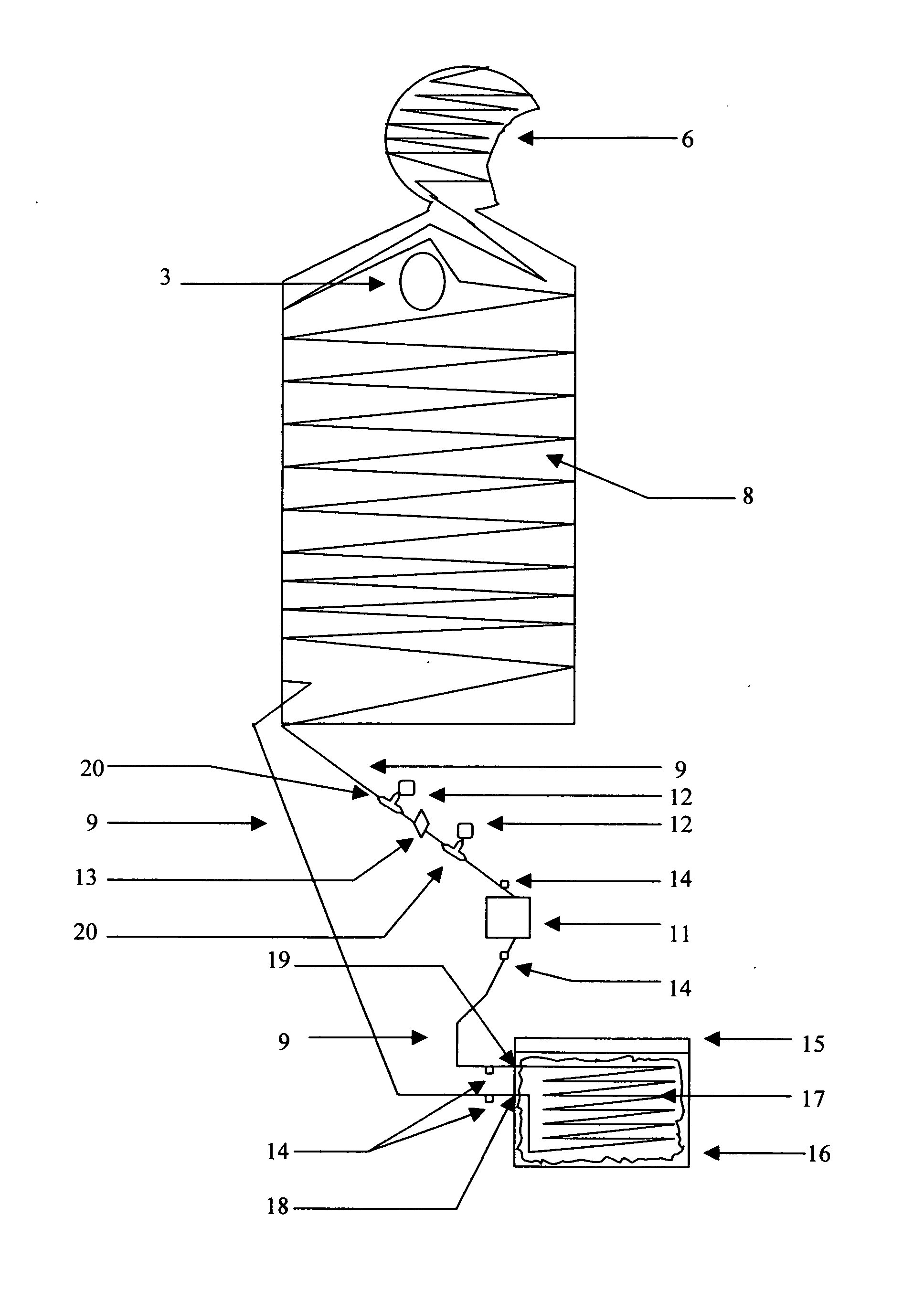
[0051]Referring to FIG. 4, shows the backside outer cool vest connection betw...


PUM


Abstract

A method and apparatus for adjusting the body temperature of a patient comprises a vest receiving at least a portion of the body and head. The vest comprises a frontal opening with adjustable Velcro adhesive for accommodating different patients and two openings for the arms with rubber-tubing coiled between two layers of fabric, one being thermal insulated. The rubber-tubing from the vest will be connected to a pump then connected to a copper-tubing coil inside a cooler to form a closed circuit loop between the rubber-tubing, copper-tubing coil and pump. Water or other liquids will be circulated via pump into vest from copper-tubing coil inside a cooler filled with ice. The vest, pump and copper coil will be portable and there will be two union connectors, two tee connectors, and a manual diverter to enable unit to also be powered via a stationary cooling motor if so desired.

Description

FIELD OF INVENTION[0001]This invention relates generally to the medical field. More particularly, the invention relates to a device to allow an adjustment of the body temperature of a patient, namely strokes and / or heart attack patients but not exclusively for these types of traumas. The aim is to induce hypothermia to prevent and / or minimize damage via maintaining an adjusted body temperature to help prevent further damage to the human body that has been traumatized due to an accident or illness.BACKGROUND OF THE INVENTION[0002]Various types of body cooling devices are well known. However, none of the references provided has a vest that cools the head and body simultaneously via coil filled with water or other liquid and is portable with a pump.[0003]The related art is represented by the following patents of interest and applications.[0004]U.S. application Ser. No. 11 / 603,846 applied on Nov. 22, 2006 by Denise Barbut & Allan Rosezenberg describes a method for cerebral and systemic ...

Claims


Application Information

Patent Timeline
Patent Type & Authority Applications(United States)
IPC IPC(8): F25D31/00A41D3/08A41D1/04
CPCA41D13/0053A61F7/02F25D2400/26A61F2007/0056A61F2007/0234A61F2007/0018
Inventor TERRY, DENNIS T.
Owner TERRY DENNIS T
Why Eureka
Try Eureka