Apparatus for extending and retracting an armor system for defeating high energy projectiles

a technology of armor system and projectile, applied in the field of armor system, can solve the problems of affecting the system and personnel of the vehicle, affecting the safety of the vehicle, and occurrence can have a very significant detrimental effect on the system and personnel within the vehicle, and troublesome vehicles using conventional armor

Inactive Publication Date: 2012-06-21
FORCE PROTECTION TECH
View PDF0 Cites 57 Cited by
  • Summary
  • Abstract
  • Description
  • Claims
  • Application Information

AI Technical Summary

Problems solved by technology

The problem is that these explosive systems are poor at defeating EFP or Hybrid systems.
Such an occurrence can, obviously, have very significant detrimental effects on the systems and personnel within a vehicle having its armor defeated in such a manner.
For that reason, and the fact that such weapons are effective, has proved troublesome to vehicles using conventional armor.
However, nets having fixed spacings from vehicles may increase an effective width of a vehicle, thereby possibly causing problems maneuvering in narrow passages, such as, e.g., in some urban environments.
While any anti-armor projectile can be defeated by metal armor of sufficient strength and thickness, extra metal armor thickness is heavy and expensive, adds weight to any armored vehicle using it which, in turn, places greater strain on the vehicle engine and drive train.

Method used


Image

  • Apparatus for extending and retracting an armor system for defeating high energy projectiles
  • Apparatus for extending and retracting an armor system for defeating high energy projectiles
  • Apparatus for extending and retracting an armor system for defeating high energy projectiles

Examples


first embodiment

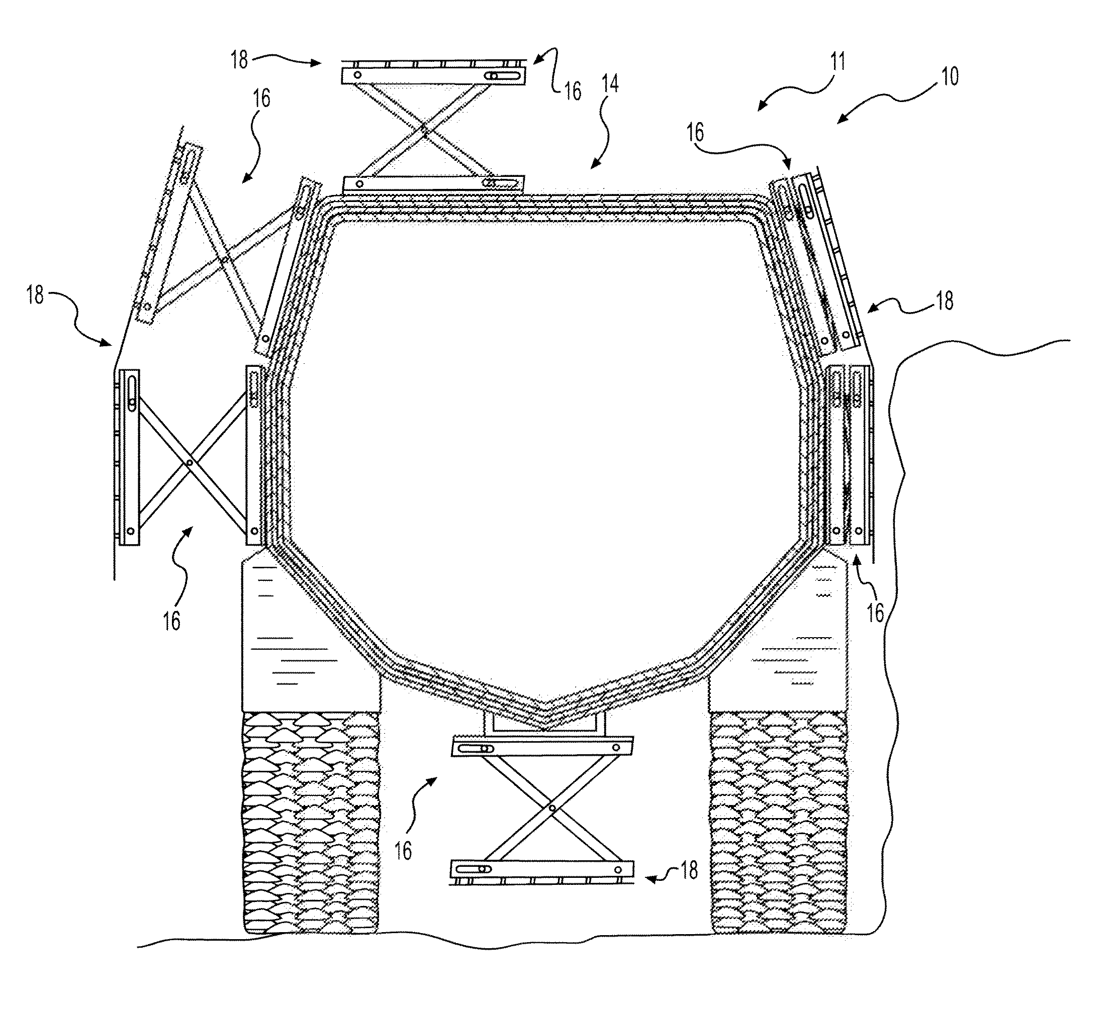
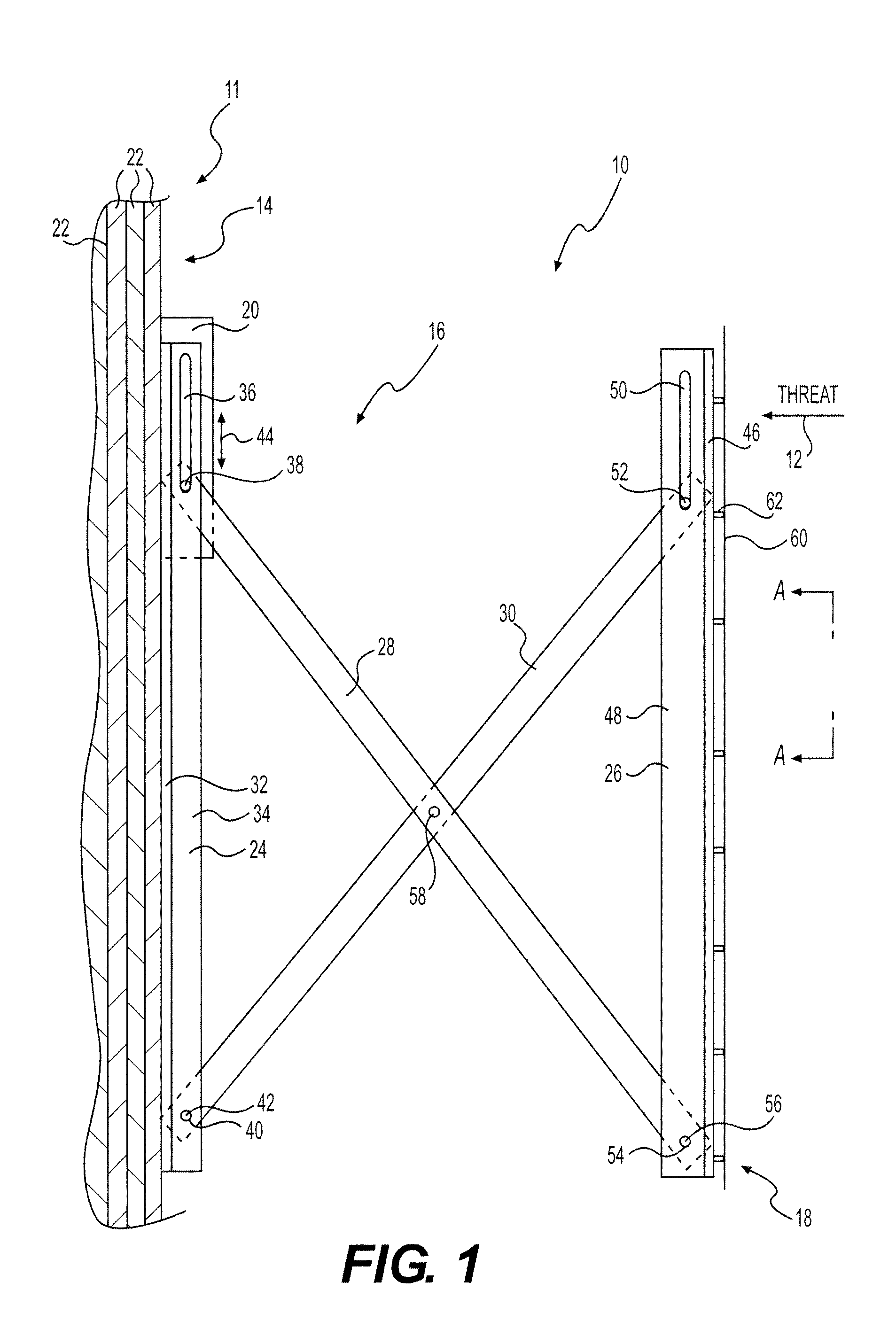
[0024]FIG. 1 illustrates an exemplary disclosed armor system 10 for protecting a vehicle 11 (shown in FIG. 4) from projectiles such as, for example, HC and Hybrid warheads. The projectiles have an expected trajectory 12 relative to vehicle 11. Armor system 10 may include an armored hull 14, at least one telescoping frame 16, at least one projectile-defeating assembly 18, and at least one jacking device 20. Telescoping frame 16 may be disposed between armored hull 14 and projectile-defeating assembly 18, and jacking device 20 may drive telescoping frame 16 to extend and retract projectile-defeating assembly 18 relative to armored hull 14.

[0025]Armored hull 14 may include a plurality of layers 22. Layers 22 may include armored layers and a vehicle hull layer, the armored layers being layered behind and / or in front of the vehicle hull layer, relative to trajectory 12. Armored hull 14 may include any number of layers 22 appropriate for defeating projectiles. Armored hull 14 may include ...

second embodiment

[0044]FIG. 5A illustrates an exemplary disclosed armor system for protecting a vehicle 111 (shown in FIG. 6). The elements of an armor system 110 may be generally similar to armor system 10. Armor system 110 may include an armored hull 114 that includes a plurality of layers 122, at least one telescoping frame 116, at least one projectile-defeating assembly 118, and at least one jacking device 120.

[0045]Each telescoping frame 116 may include a first attaching member 124 having an aperture, a second attaching member 126 having an aperture, a first cross member 128, a second cross member 130, and a support member 132. First attaching member 124 and second attaching member 126 may attach telescoping frame 116 to armored hull 114, and first and second cross members 128 and 130 may be attached to support member 132.

[0046]First cross member 128 may be a movable cross member including a first attaching member 134 having an aperture, a second attaching member 136 having an aperture, a first...

third embodiment

[0054]FIG. 7A illustrates an exemplary disclosed armor system for protecting a vehicle. The elements of an armor system 210 may be generally similar to armor system 10. Armor system 210 may include a vehicle armored hull 214 including a plurality of layers 222 similar to layers 22, at least one telescoping frame 216, at least one projectile-defeating assembly 218 that may be similar to projectile-defeating assembly 18, and at least one jacking device 220.

[0055]Each telescoping frame 216 may include an attaching member 224 having an aperture, a cross member 228, and a support member 232 having an aperture. Attaching member 224 may attach telescoping frame 216 to armored hull 214, and cross member 228 may attach support member 232 to attaching member 224. Support member 232 may support projectile-defeating assembly 218.

[0056]Cross member 228 may be a movable cross member including a first support member 238 having an aperture on each of its end portions and a second support member 240...


PUM


Abstract

An armor system for protecting a vehicle from a projectile is disclosed. The armor system includes a telescoping frame having an attaching member attaching the telescoping frame to a hull of the vehicle, a support member, and at least one movable cross member attached between the attaching member and the support member. A distance between the hull and the support member varies based on the position of the at least one cross member. The armor system also includes a projectile-defeating assembly attached to the support member.

Description

[0001]This application claims priority to U.S. Provisional Patent Application 61 / 282,091, which is hereby incorporated by reference.TECHNICAL FIELD[0002]The present disclosure relates to an armor system that resists penetration by projectiles.BACKGROUND[0003]Conventional armor, such as for protecting vehicles, is subjected to a variety of projectiles designed to defeat the armor by either penetrating the armor with a solid or jet-like object or by inducing shock waves in the armor that are reflected in a manner to cause spalling of the armor such that an opening is formed and the penetrator (usually stuck to a portion of the armor) passes through, or an inner layer of the armor spalls and is projected at high velocity without physical penetration of the armor.[0004]Some anti-armor weapons are propelled to the outer surface of the armor where a shaped charge is exploded to form a generally linear “jet” of metal that will penetrate solid armor; these are often called Hollow Charge (HC...

Claims


Application Information

Patent Timeline
Patent Type & Authority Applications(United States)
IPC IPC(8): F41H7/02F41H5/007
CPCF41H5/026F41H5/023
Inventor ENGLEMAN, GREGORY W.COLE, ROBERT A.JOYNT, VERNON P.
Owner FORCE PROTECTION TECH
Why Eureka
Try Eureka