Switchgear
- Summary
- Abstract
- Description
- Claims
- Application Information
AI Technical Summary
Benefits of technology
Problems solved by technology
Method used
Image
Examples
embodiment 1
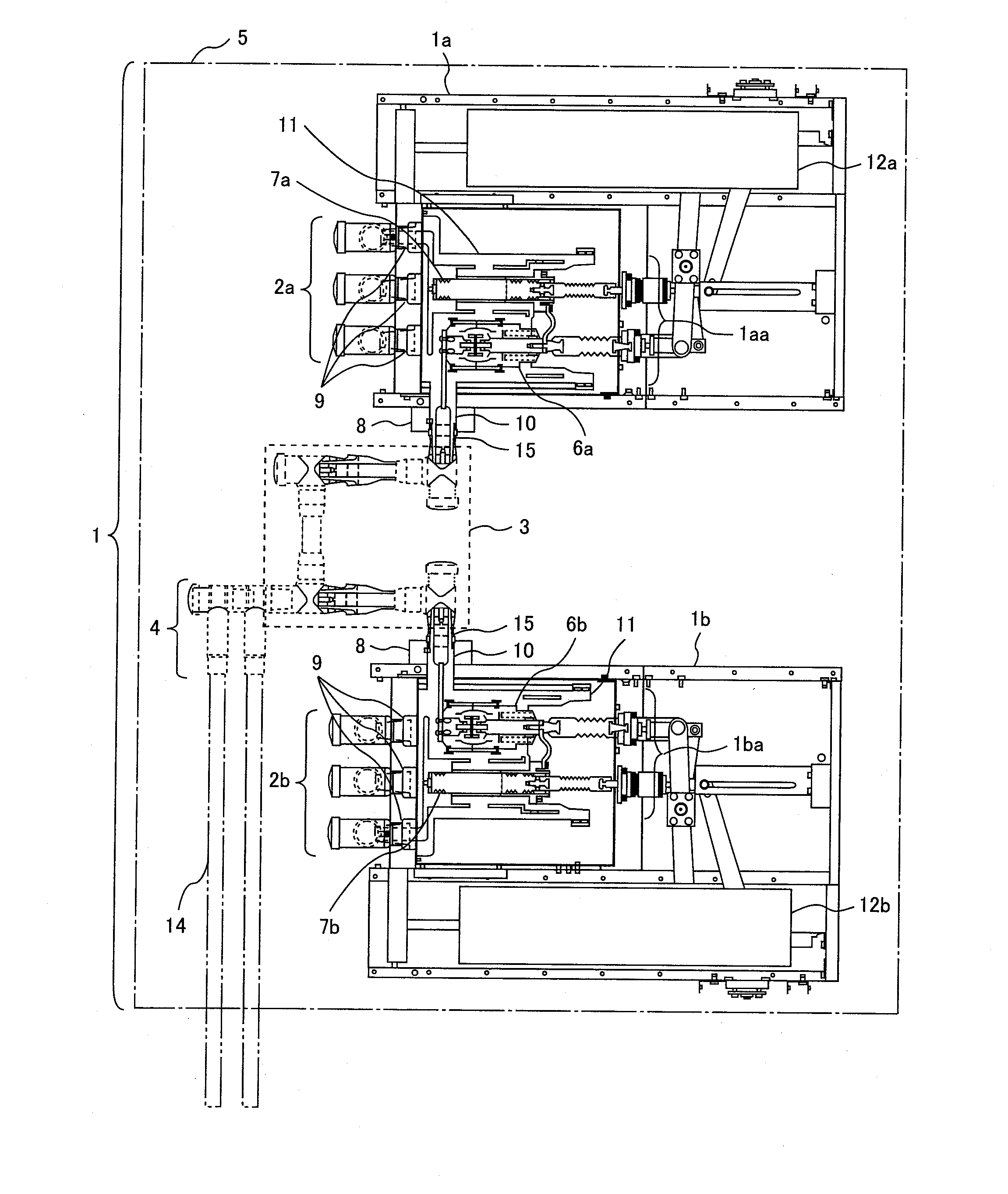
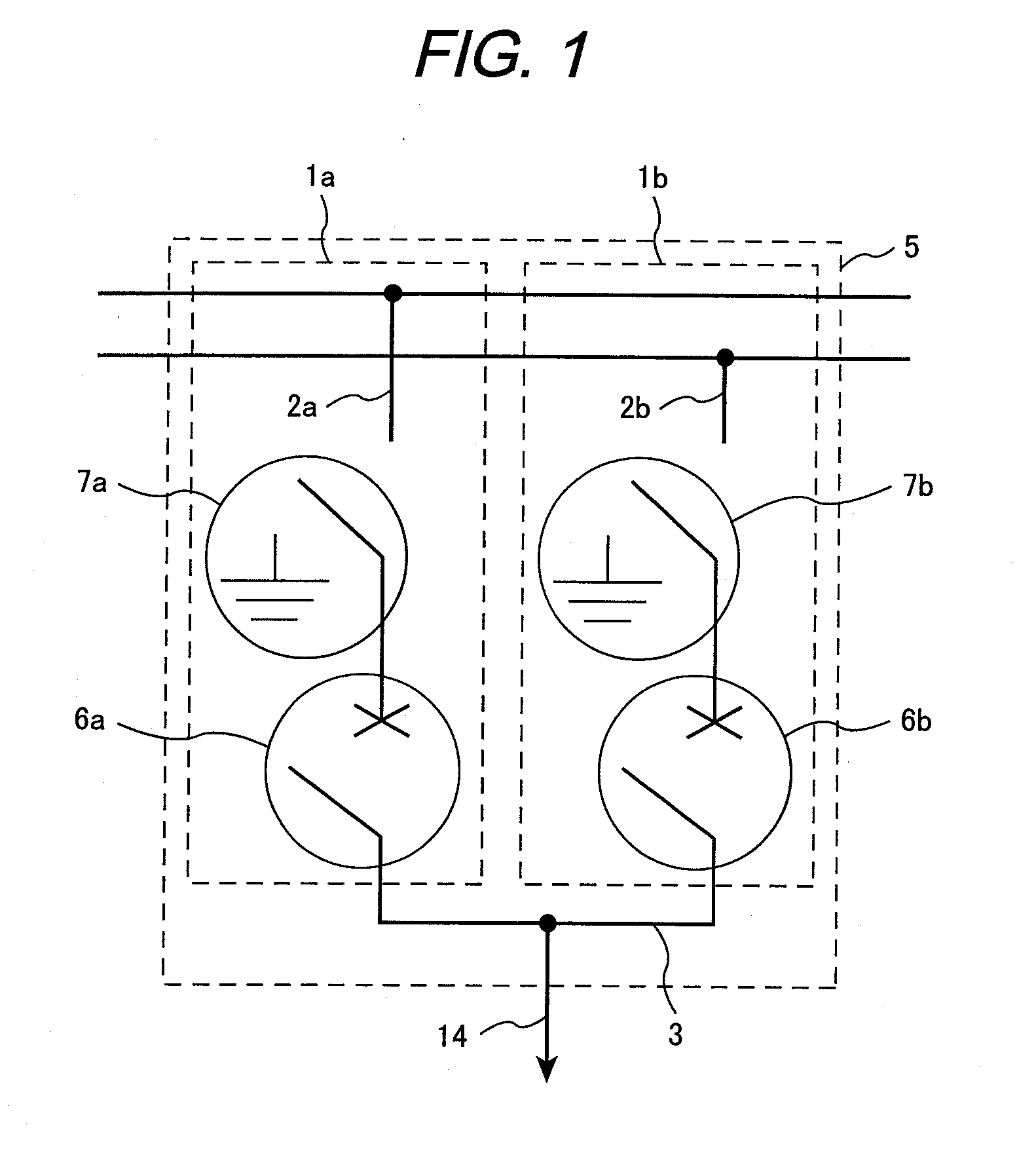
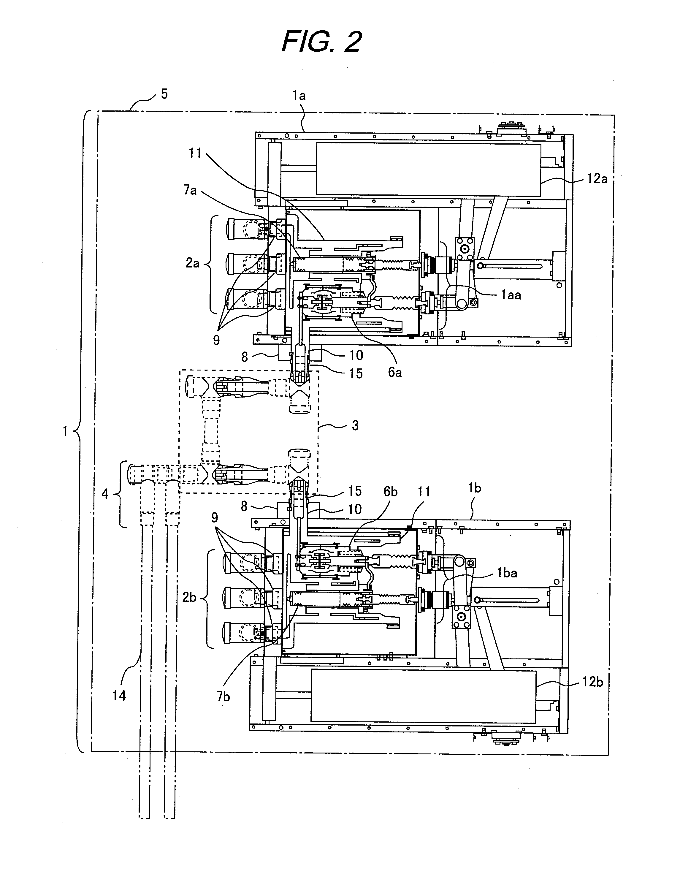
[0034]The first embodiment will be described referring to FIG. 2. The switchgear 1 of vacuum insulation type according to the embodiment includes two switch units 1a, 1b, two bus portions 2a, 2b, the solid insulated conductor 3 for connecting those two switch units 1a, 1b, the cable connection portion 4, and the housing 5 which stores the respective units as described above. The switch units 1a, 1b are vertically arranged in two upper and lower stack stages in parallel at the same side so that the bus portions 2a, 2b are directed to a back surface of the switchgear. The solid insulated conductor 3 is provided between the two switch units 1a and 1b. The cable connection portion 4 is provided closer to the back surface than the solid insulated conductor 3 at the same back side as the bus portions 2a, 2b so that the conductor connection portions 15 of the two switch units face with each other.
[0035]In the embodiment, the bus portions 2a, 2b are provided at the back side, and the cable ...
embodiment 2
[0037]The second embodiment will be described referring to FIG. 3. The embodiment has a different arrangement of the switch units from that of the embodiment 1. However, the same switch units as those used in the embodiment 1 are employed, and accordingly, the redundant explanation of the switch unit will be omitted.
[0038]In this embodiment, the switch units 1a, 1b are arranged in two upper and lower stack stages in the longitudinal direction of the switch units 1a, 1b so that the respective bus connection portions are positioned at the respective tops. The solid insulated conductor 3 is provided between the two switch units 1a, 1b, and the respective conductor connection portions 15 are arranged at the back side of the solid insulated conductor 3. The respective conductor connection portions 15 are arranged in parallel in a plane, and directed to the same side. The conductor connection portions 15 are connected with each another by conductors perpendicular thereto.
[0039]In the embo...
embodiment 3
[0041]The third embodiment will be described referring to FIG. 4. The arrangement of the switch units is different from that of the embodiment 1 or 2. However, the same switch unit as that of the embodiment 1 is employed, and accordingly, the explanation of the switch unit will be omitted.
[0042]The switch units 1a, 1b are provided at positions where the switch units 1a, 1b are displaced from the longitudinal direction and the direction perpendicular thereto so that the respective bus connection portions of the switch units 1a, 1b are positioned upward of the switchgear. The one at the lower stage side is positioned at the front side of the switchgear, and the one at the upper stage side is positioned at the back side of the switchgear. The solid insulated conductor 3 is provided between the aforementioned two switch units 1a, 1b, and the conductor connection portions 15 are arranged at the back side of the solid insulated conductor 3.
[0043]In the embodiment, a plurality of switch un...
PUM
 Abstract
Description
Claims
Application Information
 - R&D
- Intellectual Property
- Life Sciences
- Materials
- Tech Scout
- Unparalleled Data Quality
- Higher Quality Content
- 60% Fewer Hallucinations
Browse by: Latest US Patents, China's latest patents, Technical Efficacy Thesaurus, Application Domain, Technology Topic, Popular Technical Reports.
© 2025 PatSnap. All rights reserved.Legal|Privacy policy|Modern Slavery Act Transparency Statement|Sitemap|About US| Contact US: help@patsnap.com


