Input apparatus

Active Publication Date: 2012-06-21
KYOCERA CORP
View PDF2 Cites 207 Cited by
  • Summary
  • Abstract
  • Description
  • Claims
  • Application Information

AI Technical Summary

Benefits of technology

[0037]According to the present invention, the tactile sensation is provided to the object pressing the touch face based on a position of the knob of the slide bar shifted based on position information from the touch sensor while the load detection unit detects the pressure load satisfying the predetermined standard. Therefore, the input appar

Problems solved by technology

As such, when detecting an operation to the slide bar such as the track bar and the scroll bar as described above, the input apparatus having the tou

Method used


Image

  • Input apparatus
  • Input apparatus
  • Input apparatus

Examples


first embodiment

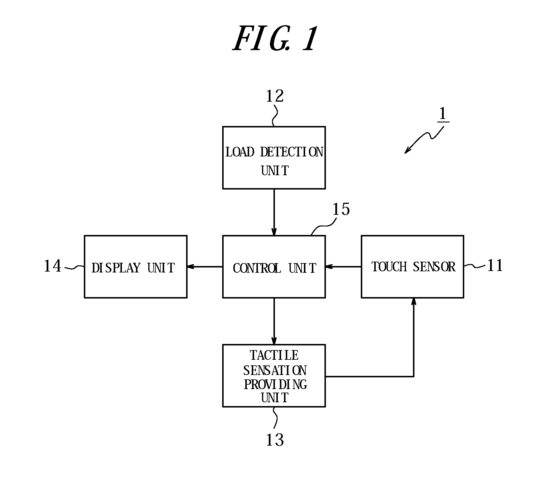
[0048]FIG. 1 is a block diagram illustrating a schematic constitution of the input apparatus according to a first embodiment of the present invention.

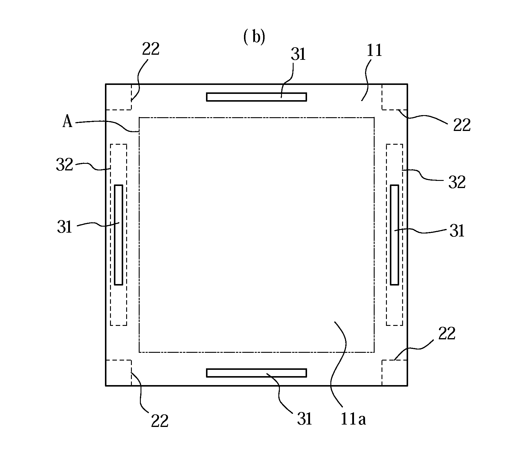
[0049]As illustrated in FIG. 1, an input apparatus 1 according to the first embodiment has a touch sensor 11, a load detection unit 12, a tactile sensation providing unit 13, a display unit 14, and a control unit 15 configured to control overall operations.

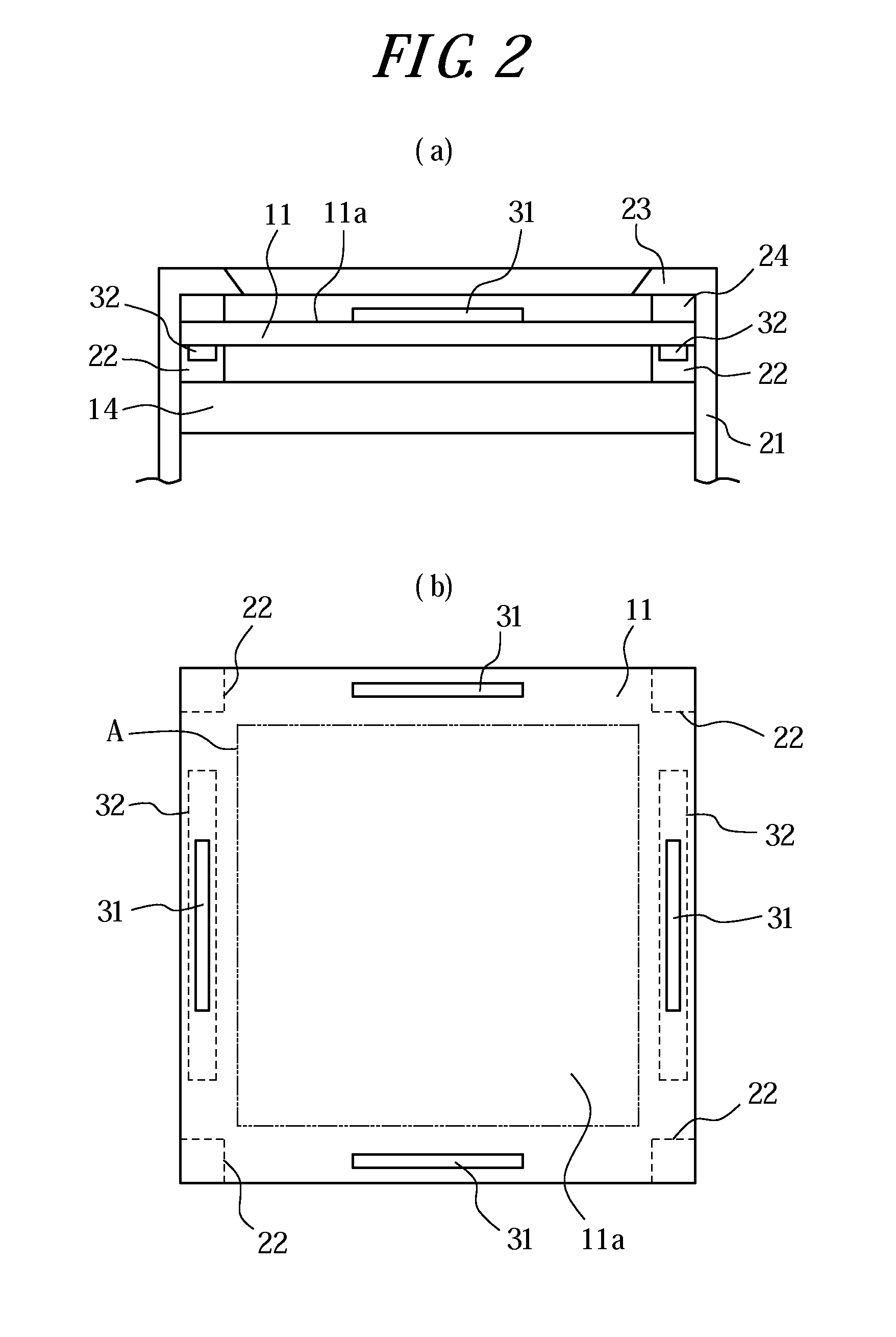
[0050]The touch sensor 11 is disposed on a front face of the display unit 14 to detect a pressing input (contact) to a key and a button (hereinafter, referred to simply as a “key and the like”) displayed on the display unit 14 by an operator's finger or the like on a corresponding touch face of the touch sensor 11. The touch sensor 11 may be, for example, of a known type such as a resistive film type, a capacitive type, an optical type or the like. The load detection unit 12 detects a pressure load on the touch face of the touch sensor 11 and may include an element such as, for examp...

second embodiment

[0100]Next, an input apparatus according to a second embodiment of the present invention will be described. An input apparatus 2 according to the second embodiment may have the same constitution as that of the input apparatus 1 described in the first embodiment but partially alters the operation according to the first embodiment. Hence, the same descriptions as those of the first embodiment will be appropriately omitted.

[0101]The input apparatus 2 according to the second embodiment also operates based on the flowchart described with reference to FIG. 3. In addition, according to the second embodiment as well, the control unit 15 controls the tactile sensation providing unit 13 such that the tactile sensation is provided based on the position of the knob of the slide bar shifted in response to the contact detected by the touch sensor 11 while the load detection unit 15 is detecting the pressure load satisfying the predetermined standard. From this point of view, the input apparatus 2...

third embodiment

[0120]Next, an input apparatus according to a third embodiment of the present invention will be described. An input apparatus 3 according to the third embodiment may have the same constitution as that of the input apparatus 1 described in the first embodiment and performs the operation according to the second embodiment in a partially altered manner. Hence, the same descriptions as those of the first and second embodiments will be appropriately omitted.

[0121]The input apparatus 3 according to the third embodiment also operates based on the flowchart described with reference to FIG. 3. In addition, according to the third embodiment as well, the control unit 15 controls the tactile sensation providing unit 13 such that the tactile sensation is provided based on the position of the knob of the slide bar shifted in response to the contact detected by the touch sensor 11 while the load detection unit 15 is detecting the pressure load satisfying the predetermined standard. From this point...


PUM


Abstract

Provided is an input apparatus having a touch sensor to detect a contact operation to a slide bar displayed and to provide a tactile sensation of shift of the slide bar.
An input apparatus 1 has a touch sensor 11 configured to detect a contact, a load detection unit 12 configured to detect a pressure load on a touch face of the touch sensor 11, a display unit 14 configured to display the slide bar, a tactile sensation providing unit 13 configured to vibrate the touch face, and a control unit 15 configured to control the tactile sensation providing unit 13 such that a tactile sensation is provided to an object pressing the touch face based on a position of a knob of the slide bar shifted in response to the contact detected by the touch sensor 11 while the pressure load detected by the load detection unit 12 satisfies a predetermined standard.

Description

CROSS REFERENCE TO RELATED APPLICATION[0001]This application claims priority to and the benefit of Japanese Patent Application No. 2009-197347 filed on Aug. 27, 2009, the entire contents of which are incorporated herein by reference.TECHNICAL FIELD[0002]The present invention relates to an input apparatus having a touch sensor.BACKGROUND ART[0003]In recent years, there are mobile terminals such as mobile phones that employ the input apparatus having touch sensors, such as touch panels, touch switches and the like, as the input apparatus such as operation units, switches and the like to receive contact operations by users. Such input apparatus having touch sensors are popularly employed not only by the mobile terminals but also by information equipments such as calculators, ticket vending machines, home electric appliances such as microwaves, TV sets and lighting equipment, industrial equipment (FA equipment) and the like.[0004]There are a variety of known types of those touch sensors...

Claims


Application Information

Patent Timeline
IPC IPC(8): G06F3/041
CPCG06F3/016G06F2203/04105G06F3/04855G06F3/0414
Inventor KONO, KENJI
Owner KYOCERA CORP
Why Eureka
Try Eureka