
Display apparatus and display apparatus driving method

a technology of display apparatus and driving method, which is applied in the direction of instruments, computing, electric digital data processing, etc., can solve the problems of increasing the scale of the control circuit and complicated control

Active Publication Date: 2012-06-21
JOLED INC
View PDF6 Cites 15 Cited by
  • Summary
  • Abstract
  • Description
  • Claims
  • Application Information

AI Technical Summary

Benefits of technology

[0009]Therefore, it is desirable to provide a display apparatus which can compensate for a fall in luminance due to a burn-in phenomenon without sequentially storing a history of luminance of a displayed image, a history of the operating time, and a history of a temperature condition of a display panel during operation as data but by reflecting the histories, or to provide a display apparatus driving method which can compensate for the fall in luminance due to a burn-in phenomenon by reflecting the histories.
[0012]In the display apparatus according to the embodiment, it is possible to compensate for a fall in luminance due to the burn-in phenomenon without sequentially storing a history of the luminance of a displayed image, a history of an operating time, and a history of a temperature condition of a display panel during operation as data but by reflecting the histories.

Problems solved by technology

In a method of measuring temporal variation data plural times in advance when variously changing the luminance or the temperature condition and compensating for the fall in luminance due to the burn-in phenomenon with reference to a table storing the measured data, there is a problem in that the scale of the control circuit increases and the control is complicated.

Method used


Image

  • Display apparatus and display apparatus driving method
  • Display apparatus and display apparatus driving method
  • Display apparatus and display apparatus driving method

Examples


example 1

[0068]Example 1 relates to a display apparatus and a display apparatus driving method according to an embodiment of the present disclosure.

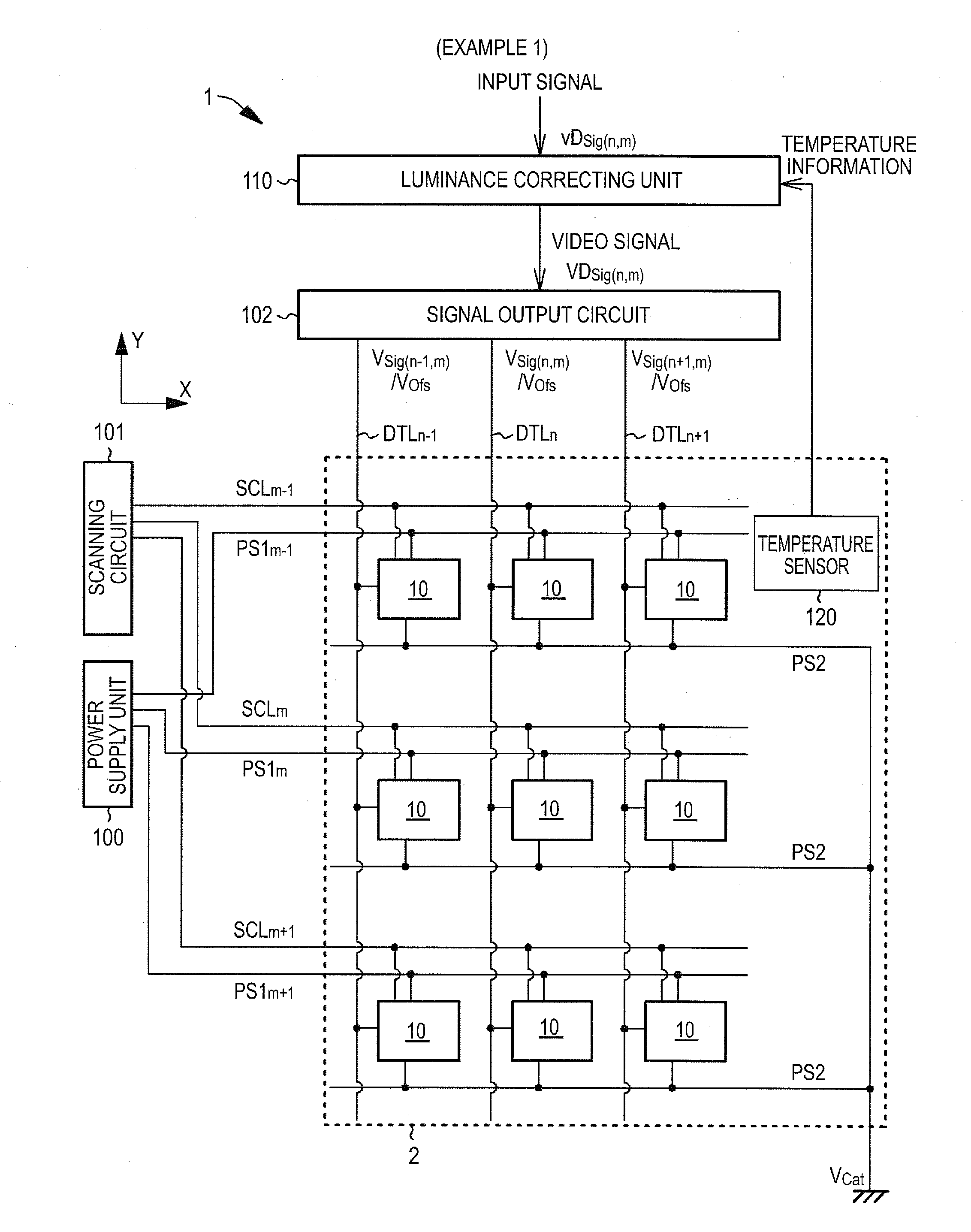
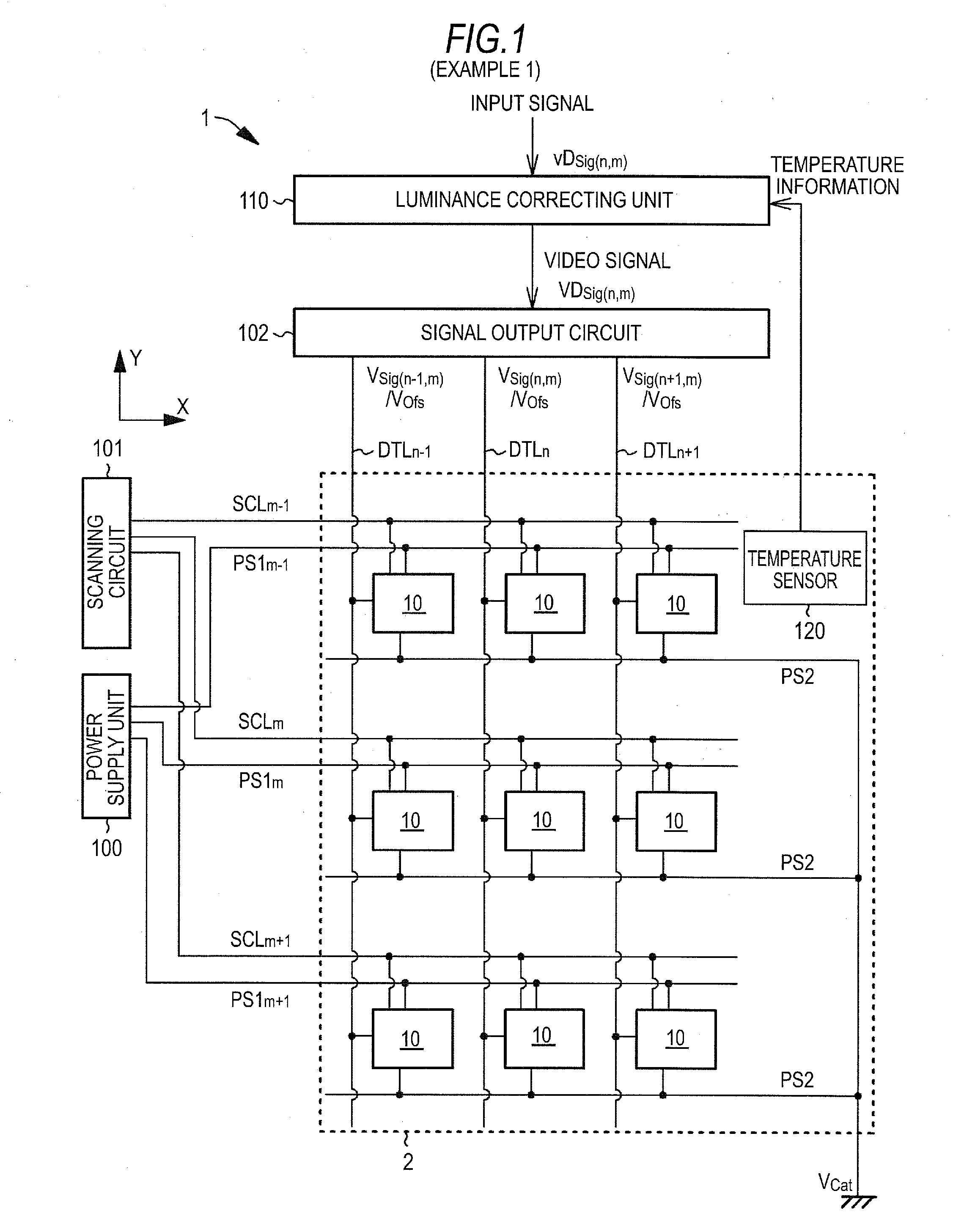
[0069]FIG. 1 is a conceptual diagram illustrating the display apparatus 1 according to Example 1. The display apparatus 1 according to Example 1 includes a display panel 2 in which display elements 10 each having a current-driven light-emitting portion are arranged in a two-dimensional matrix in a first direction and a second direction and that displays an image on a video signal VDSig and a luminance correcting unit 110 that corrects the luminance of the display elements 10 when displaying an image on the display panel 2 by correcting the gradation value of the input signal vDSig and outputting the corrected input signal as the video signal VDSig. In Example 1, the light-emitting portion is constructed by an organic electroluminescence light-emitting portion.

[0070]The display apparatus 1 further includes a temperature sensor 120. The temperature...


PUM


Abstract

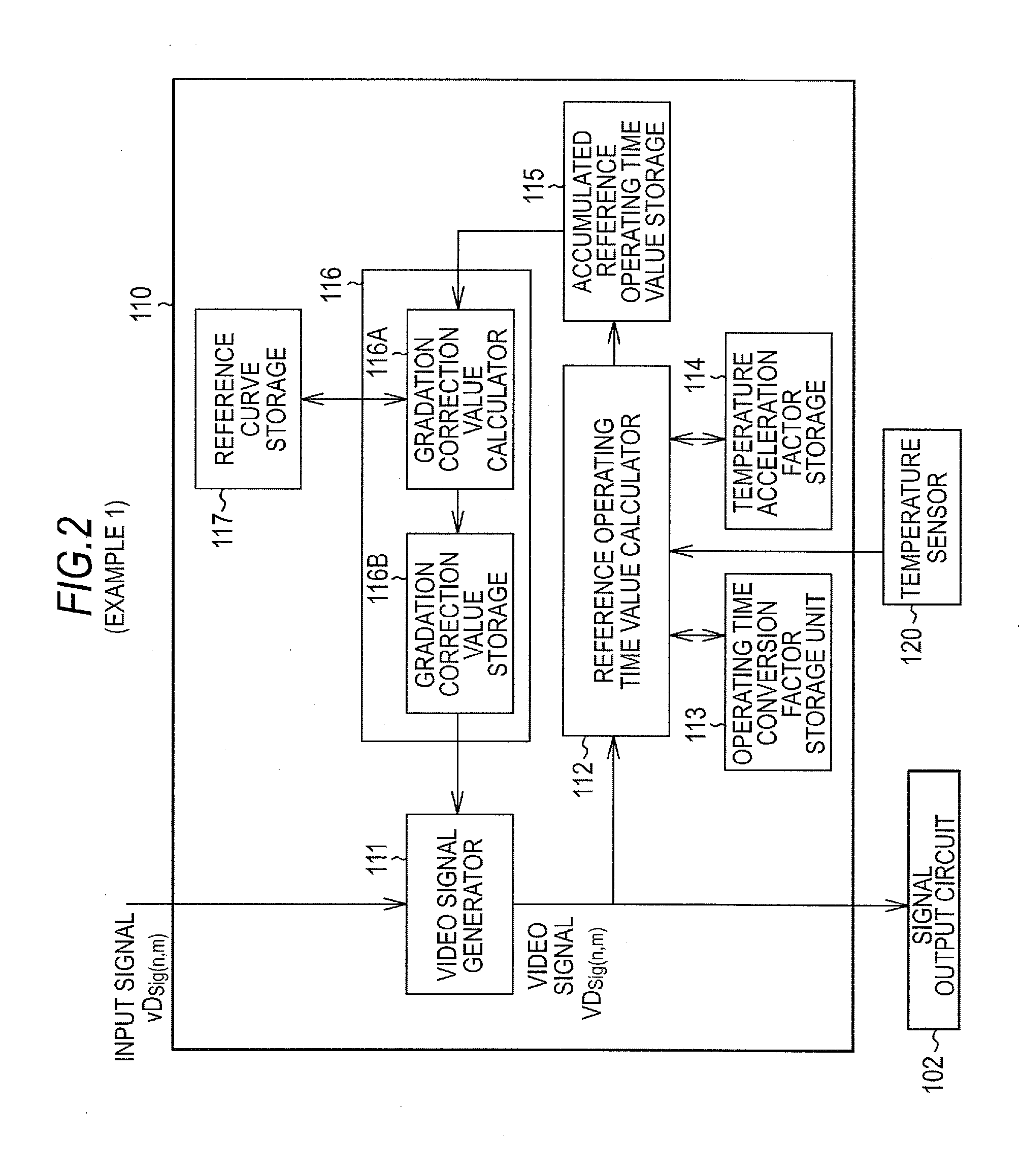
A display apparatus includes: a display panel that includes display elements having a current-driven light-emitting portion, in which the display elements are arranged in a two-dimensional matrix in a first direction and a second direction, and that displays an image on the basis of a video signal; and a luminance correcting unit that corrects the luminance of the display elements when displaying an image on the display panel by correcting a gradation value of an input signal and outputting the corrected input signal as the video signal. The luminance correcting unit includes a reference operating time calculator, an accumulated reference operating time storage, a reference curve storage, a gradation correction value holder, and a video signal generator.

Description

FIELD[0001]The present disclosure relates to a display apparatus and a display apparatus driving method.BACKGROUND[0002]Display elements having a light-emitting portion and display apparatuses having such display elements are widely known. For example, a display element (hereinafter, also simply abbreviated as an organic EL display element) having an organic electroluminescence light-emitting portion using the electroluminescence (hereinafter, also abbreviated as EL) of an organic material has attracted attention as a display element capable of emitting light with high luminance through low-voltage DC driving.[0003]Similarly to a liquid crystal display, for example, in a display apparatus (hereinafter, also simply abbreviated as an organic EL display apparatus) including organic EL display elements, a simple matrix type and an active matrix type are widely known as a driving type. The active matrix type has a disadvantage that the structure is complicated but has an advantage that t...

Claims


Application Information

Patent Timeline
IPC IPC(8): G09G5/10G09G3/30
CPCG09G3/3225G09G2320/0285G09G2320/048G09G2320/045G09G2320/046G09G2320/041
Inventor YAMASHITA, JUNICHIUCHINO, KATSUHIDE
Owner JOLED INC
Learn More