
360-degree camera head for unmanned surface sea vehicle

a camera head and unmanned surface technology, applied in the direction of color television details, television system details, television systems, etc., can solve the problems of inability to fully realize the autonomous navigation and control of the ussv, the deck mounted visual sensing system, and the operation of the vehicle is inevitably subject to the most excruciating conditions, and the inability to fully realize the autonomous navigation and control

Inactive Publication Date: 2012-06-21
CALIFORNIA INST OF TECH
View PDF38 Cites 67 Cited by
  • Summary
  • Abstract
  • Description
  • Claims
  • Application Information

AI Technical Summary

Benefits of technology

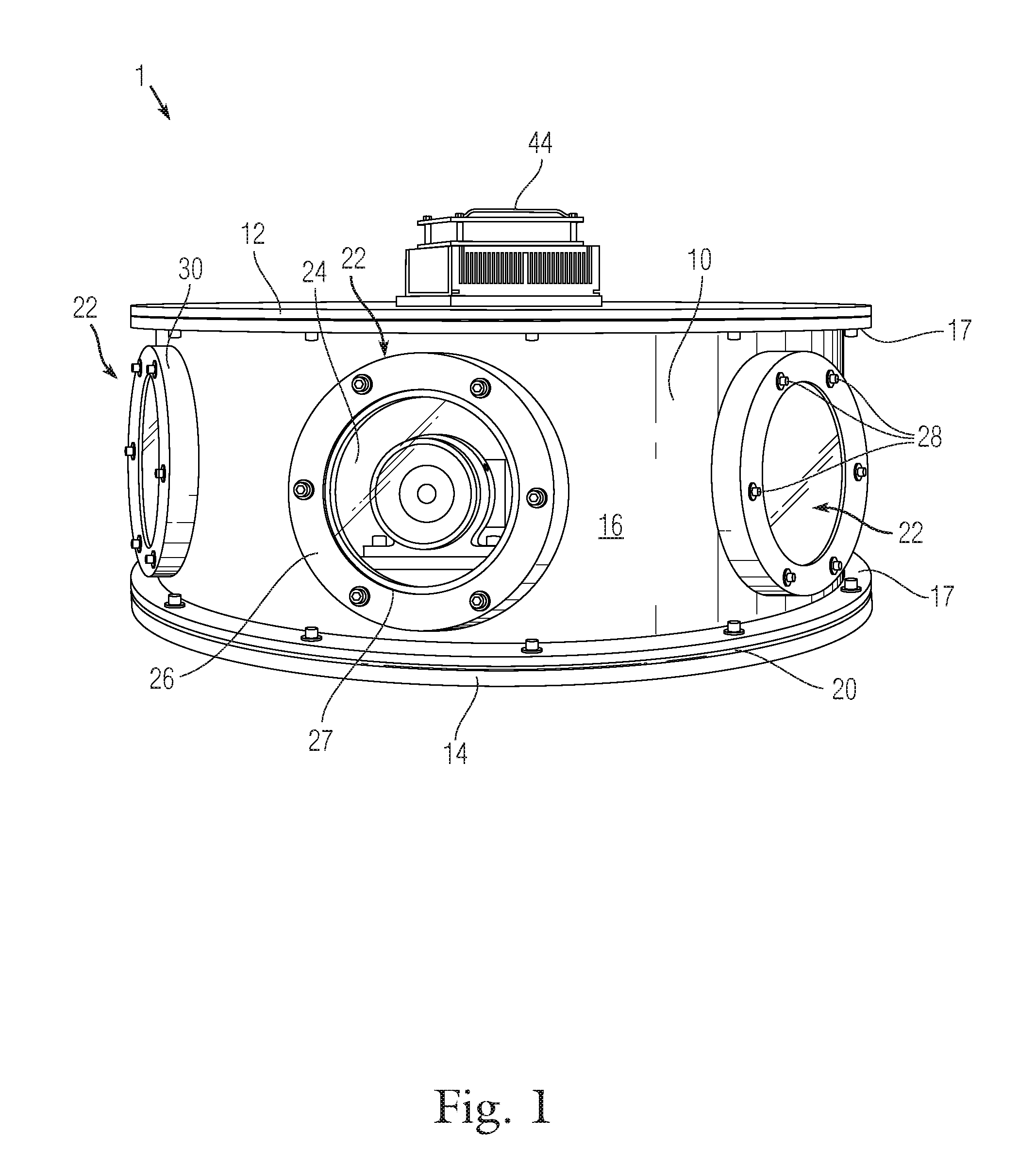
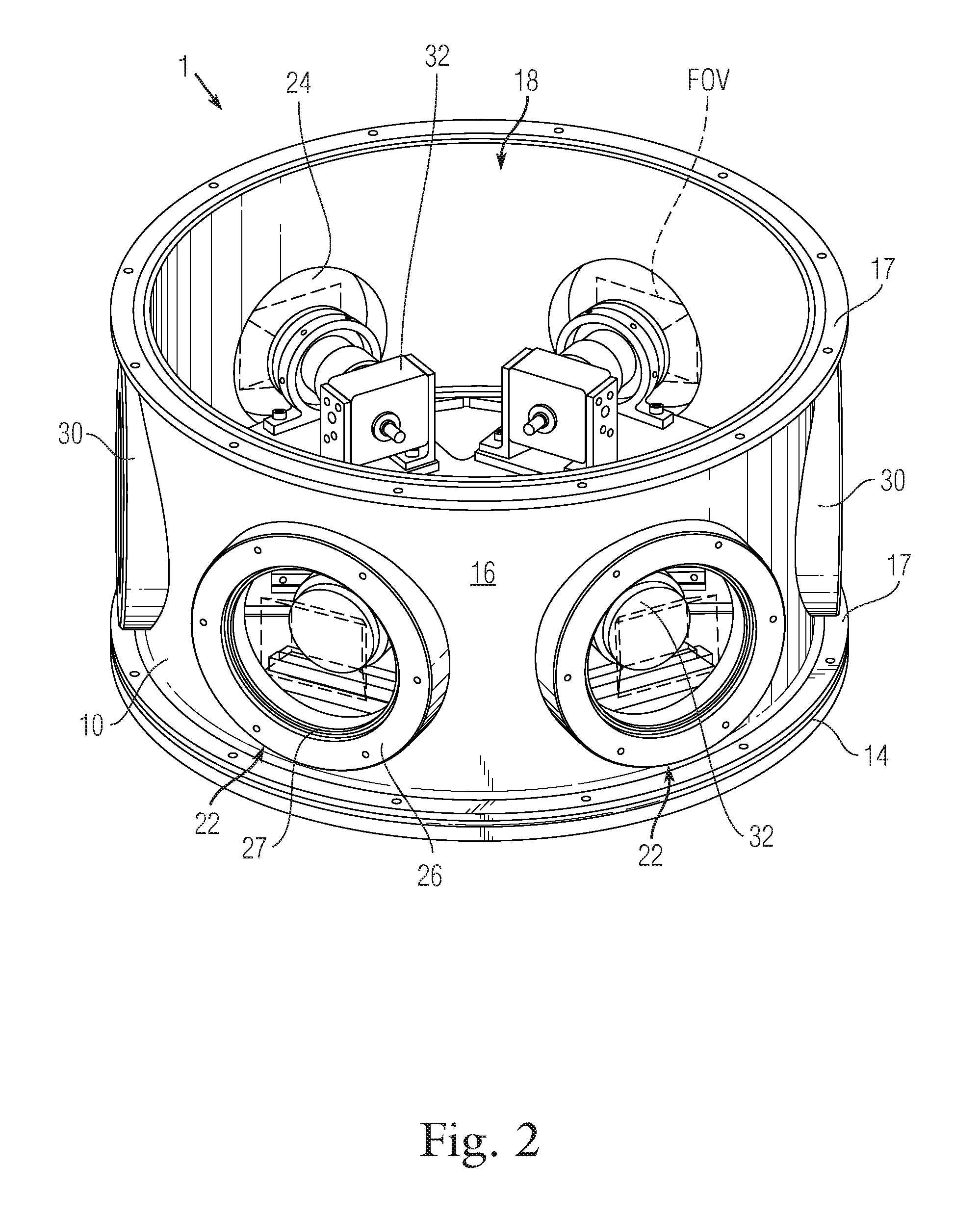
The present invention provides a camera head for use on surface sea vehicles that offers a continuous 360-degree view. The camera head is designed to be impervious to weather and sea spray, as well as unaffected by constant motion, acceleration, and repeated shock. It also maintains an internal climate controlled condition. The camera head is housed in a watertight housing with a continuous vertical surface and multiple viewing ports. Each port is equipped with a corresponding camera and a transparent element to ensure a continuous view. The camera head is ventilated and contains power and image processing and control systems, making it self-contained.

Problems solved by technology

Autonomous navigation and control of USSV's presents a significant challenge.
However, a deck mounted visual sensing system, including both optics and electronics, is inevitably subjected to the most excruciating conditions during operation including inclement weather, corrosive sea spray, constant motion and acceleration and repeated mechanical shock.
Such systems are inherently prone to significant blind spots, slow reaction times and inefficient operation.
However, such systems have a limited field of view at any given time and are prone to wear and failure of their mechanical systems due to the constant motion, shock and environmental exposure.

Method used


Image

  • 360-degree camera head for unmanned surface sea vehicle
  • 360-degree camera head for unmanned surface sea vehicle
  • 360-degree camera head for unmanned surface sea vehicle

Examples


Embodiment Construction

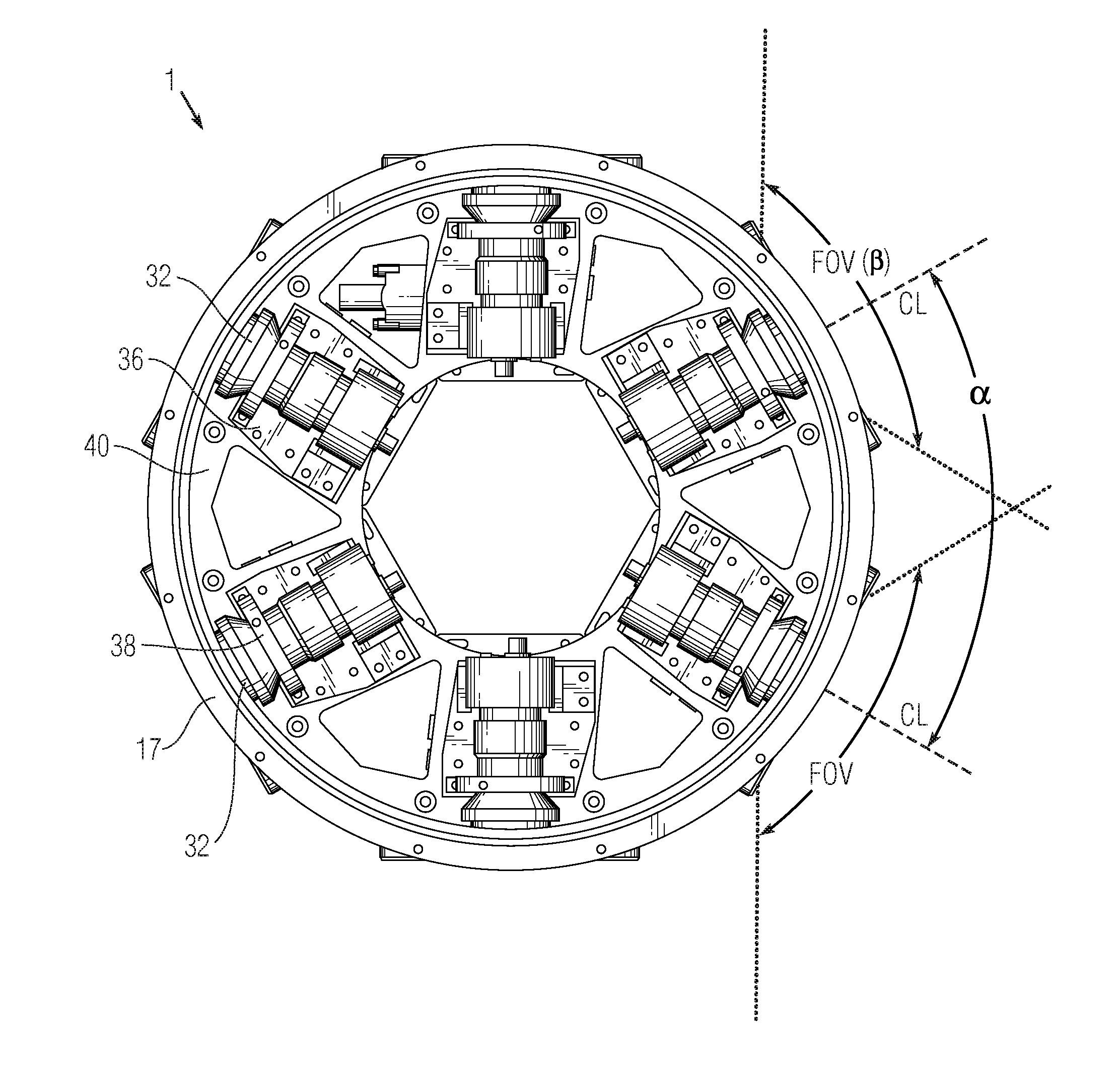
[0019]The present invention discloses a 360-degree camera head suitable for use in harsh marine environments to provide a continuous, 360-degree field of view for control and navigation of a vessel. The camera head incorporates a sealed, climate controlled housing having multiple ports through which optical sensors (i.e., cameras in a preferred embodiment) may be positioned with overlapping fields of view in order to provide total 360 degree situational awareness.

[0020]With reference to FIG. 1, the camera head 1 includes a housing 10 constructed from a strong, water impervious material such as steel, aluminum or fiber composite. The housing 10 preferably has a circular top and bottom panel 12, 14, respectively, that are attached to a hollow cylindrical body 16 defined by vertical sidewalls. The diameter of the cylindrical body 16 of the preferred embodiment is preferably from 16 to 24 inches and most preferably 20 inches. It should be noted that terms describing the relative orienta...


PUM


Abstract

A camera head for use in a marine environment having a cylindrical watertight housing, top and bottom plate members closing the cylindrical housing, and a plurality of ports through the vertical wall of the housing and positioned at a regular angular intervals. A transparent pane is sealed over each port, retained in place by compression against a gasket or O-ring by a compression member. A corresponding plurality of cameras are fixedly positioned behind the ports and the angular field of view of each camera is selected to be greater than the angular interval between the ports such that a continuous 360-degree view of the marine environment is always visible. Six 72-degree FOV cameras spaced at regular 60-degree intervals are preferred. The housing contains cooling / ventilation as well as power and image processing and control systems so as to be self contained.

Description

CROSS-REFERENCE TO RELATED APPLICATIONS[0001]The present application claims priority to U.S. provisional patent application Ser. No. 61 / 406,881 filed Oct. 26, 2010 that is incorporated herein by reference.STATEMENT OF GOVERNMENT RIGHTS[0002]This invention was made with government support under funding project N0001411IP20042 awarded by the United States Navy. The government has certain rights in the invention.BACKGROUND OF THE INVENTION[0003]1. Field of the Invention[0004]The present invention relates to visual sensing systems for autonomous control of an unmanned sea surface vehicle (USSV) and, more specifically, to a watertight camera head for providing a 360-degree view of a vehicle's surroundings.[0005]2. Description of the Background[0006]Unmanned vehicles are increasingly among the systems available to commercial enterprise and the military for surveillance, monitoring and patrol of areas by land, sea and air. Unmanned vehicles may be remotely operated in real time via robust ...

Claims


Application Information

Patent Timeline
Patent Type & Authority Applications(United States)
IPC IPC(8): H04N5/225
CPCH04N5/247H04N5/23238H04N23/698H04N23/90
Inventor TOWNSEND, JULIE A.WILLSON, REGINALD G.GARRETT, MICHAEL S.BERGH, CHARLES F.KULCZYCKI, ERIC A.HUNTSBERGER, TERRANCETREBI-OLLENNU, ASHITEY
Owner CALIFORNIA INST OF TECH
Learn More