Imaging apparatus and imaging method

a technology of imaging apparatus and image, which is applied in the direction of electrical apparatus, color television details, color signal processing circuit, etc., can solve the problems of inability to avoid image quality degradation due to a change in exposure time, inability to synchronize frame rate with light source power frequency, and inability to photograph image luminance noise, etc., to achieve improved image method, increase in calculation amount, and improve image quality

Inactive Publication Date: 2012-06-21
SAMSUNG ELECTRONICS CO LTD
View PDF7 Cites 43 Cited by
  • Summary
  • Abstract
  • Description
  • Claims
  • Application Information

AI Technical Summary

Benefits of technology

[0008]Accordingly, the present invention has been made to solve the above-mentioned problems occurring in conventional devices, and an aspect of the present invention provides an improved imaging apparatus which can detect a flicker properly while restraining an increase in an amount of calculation and a degradation of an image quality, and an improved image method.

Problems solved by technology

When an image is photographed using an electronic imaging apparatus, such as a digital camera, in an interior environment that is illuminated by a fluorescent light, an illuminance of a subject being photographed will occasionally change periodically, causing luminance noise in the photographed image.
However, in Japanese Patent Application Publication No. 2009-130531, the frame rate cannot be synchronized with a power frequency of a light source.
However, when a flicker component is extracted by varying an exposure time, as described in Japanese Patent Application Publication No. 2010-520673, a degradation of an image quality due to a change in exposure time cannot be avoided.

Method used


Image

  • Imaging apparatus and imaging method
  • Imaging apparatus and imaging method
  • Imaging apparatus and imaging method

Examples


Embodiment Construction

[0026]Hereinafter, embodiments of the present invention will be described in detail with reference to the accompanying drawings. In the following description of the present invention and the drawings, the same or like reference numerals denote the elements having substantially the same functional configurations, and a description thereof will not be repeated.

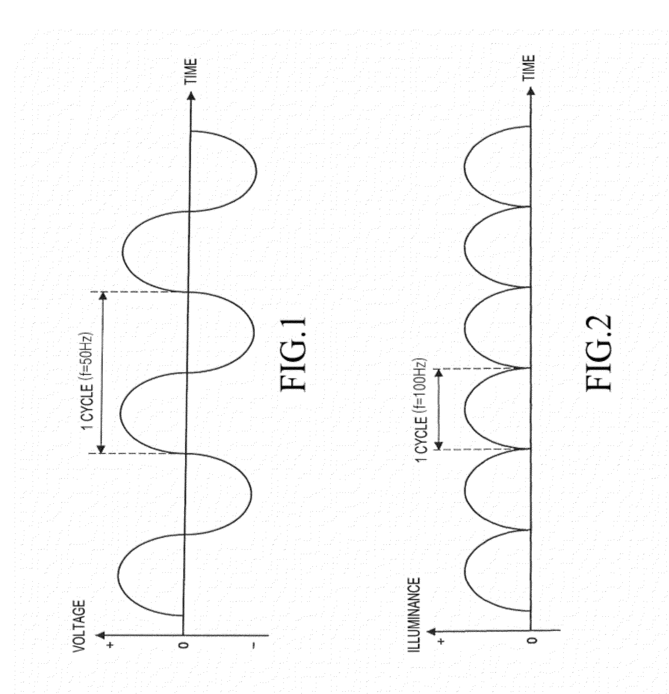
[0027]The principle of generation of a flicker is first described. As described above, a flicker refers to a periodic change in an illuminance of a subject. An illuminance change of a subject is caused by an illuminance change of a light source, and an illuminance change of a light source is caused by a voltage change.

[0028]FIG. 1 is a graph illustrating an example of a voltage change of an AC power. As illustrated in FIG. 1, a voltage change in Alternating Current (AC) power corresponds to a sine wave. Since a frequency of AC power is generally 50 Hz or 60 Hz, a voltage change of the AC power shows a sine wave of a frequency (f...


PUM


Abstract

Disclosed is an imaging apparatus with a flicker detector that restrains an increased calculation amount and image quality degradation. The apparatus includes a frame rate controller for setting a frame rate of an acquired image to a first frame rate or different second frame rate, a luminance calculator for calculating a first luminance difference between two images of a first group continuously acquired at the first frame rate and a second luminance difference between two images of a second group continuously acquired at the second frame rate, and a flicker detector for comparing the first and second luminance differences with first and second threshold, respectively, and determining whether flickers of a first frequency and a different second frequency are generated or not.

Description

PRIORITY[0001]This application claims priority under 35 U.S.C. §119(a) to an application filed in the Japanese Patent Office on Dec. 20, 2010, and assigned Serial No. 2010-283671, the contents of which are incorporated herein by reference.BACKGROUND OF THE INVENTION[0002]1. Field of the Invention[0003]The present invention generally relates to an imaging apparatus and an imaging method, and more particularly to an imaging apparatus having an automatic exposure function, and an image method.[0004]2. Description of the Related Art[0005]When an image is photographed using an electronic imaging apparatus, such as a digital camera, in an interior environment that is illuminated by a fluorescent light, an illuminance of a subject being photographed will occasionally change periodically, causing luminance noise in the photographed image. The periodic changes in the illuminance of the subject is referred to herein as a flicker. The luminance noise generated in the image by the flicker is re...

Claims


Application Information

Patent Timeline
Patent Type & Authority Applications(United States)
IPC IPC(8): H04N9/73
CPCH04N7/0127H04N23/70H04N25/60
Inventor HORIUCHI, SATOSHI
Owner SAMSUNG ELECTRONICS CO LTD
Why Eureka
Try Eureka