Automatic analyzer

a technology of automatic analysis and analyzer, which is applied in the direction of fluid controllers, instruments, laboratory glassware, etc., can solve the problems of inability to obtain reliable analysis results, abnormalities, and abnormalities, and achieve the effects of increasing the calculation amount, reducing the determination performance, and high degree of accuracy

Active Publication Date: 2021-11-09
HITACHI HIGH-TECH CORP
View PDF13 Cites 0 Cited by
  • Summary
  • Abstract
  • Description
  • Claims
  • Application Information

AI Technical Summary

Benefits of technology

[0020]According to the present invention, it is possible to implement an automatic analyzer which is capable of detecting a dispensing abnormality with a high degree of accuracy without causing the decrease in the determination performance or the increase in the calculation amount caused by the configuration balance of the reference database.

Problems solved by technology

In the process of dispensing the specimen to the reaction container, one of factors that frequently causes the dispensing abnormality is probe clogging caused by suction of a solid foreign substance such as fibrin.
If the clogging occurs in the probe, a predetermined amount of specimen is unable to be dispensed to the reaction container, and thus a reliable analysis result is unable to be obtained.
Further, when there are bubbles or a liquid film on a liquid level of a specimen to be tested, the bubbles or the liquid film are determined to be the liquid level, an amount of specimen that has to be sucked originally is unable to be sucked, leading to a dispensing abnormality.
In order to prevent the dispensing abnormality when there are the bubbles or the liquid film, an immersion amount of the probe in the specimen to be tested may be increased, but if the immersion amount of the probe in the specimen is increased, contamination may increase, and thus, an analysis result may be adversely affected.
However, when a liquid level sensor is used, as described above, if there are bubbles or a liquid film on the liquid level, they are likely to be erroneously detected as the liquid level, leading to a dispensing abnormality.
In the process of dispensing the reagent to the reaction container, the dispensing abnormality may occur when air bubbles generated on a reagent liquid level are sucked.
If the immersion amount of the probe in the reagent is increased as in the case of the specimen, contamination may increase, and thus, an analysis result may be adversely affected.

Method used


Image

  • Automatic analyzer
  • Automatic analyzer
  • Automatic analyzer

Examples


embodiments

First Embodiment

(1) Overall Structure of Automatic Analyzer

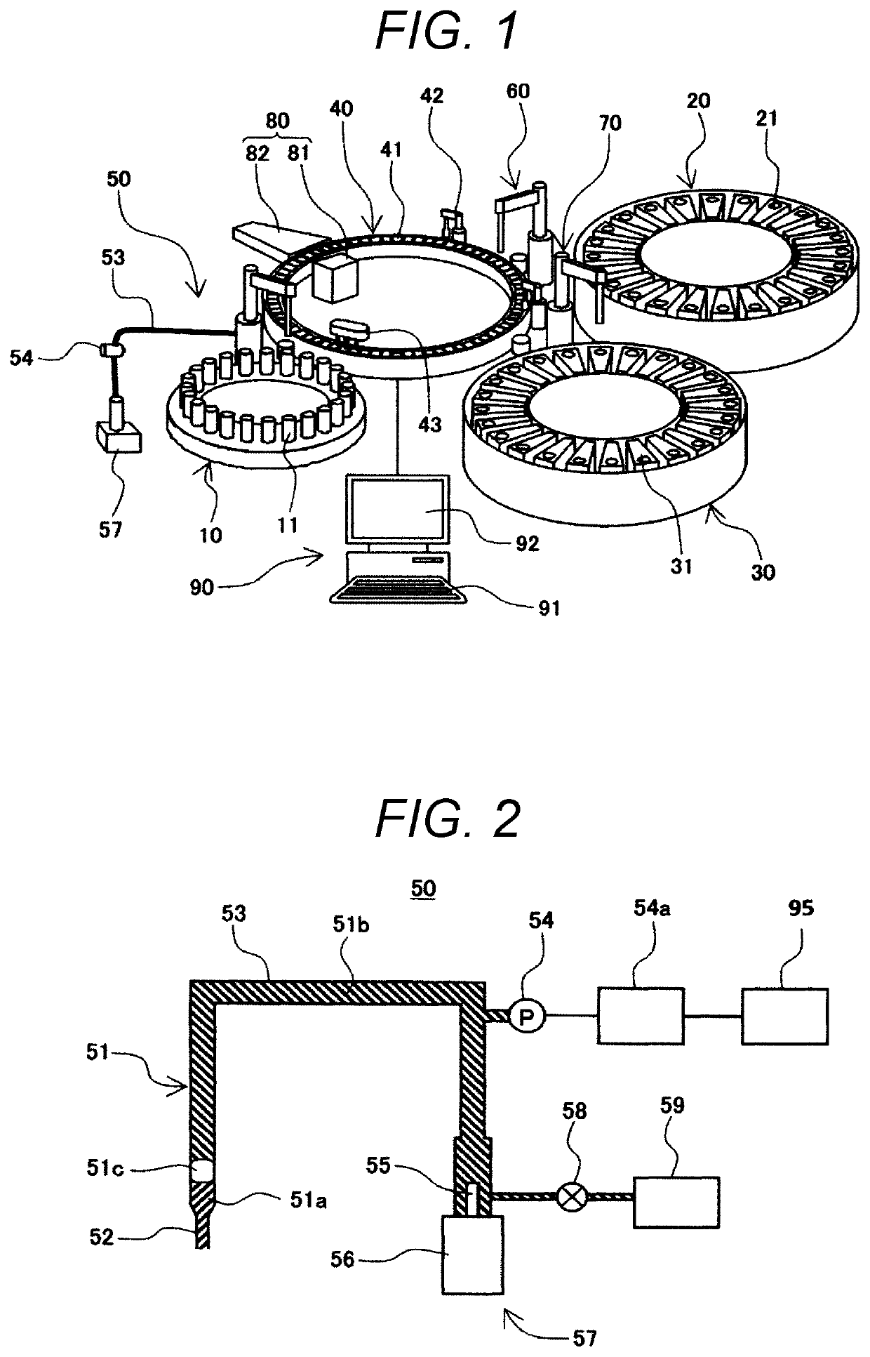
[0034]FIG. 1 is an overall schematic configuration diagram of an automatic analyzer to which the present invention embodiment is applied.

[0035]Referring to FIG. 1, an automatic analyzer includes a sample disk 10, a first reagent disk 20, a second reagent disk 30, a reaction disk 40, a sample dispensing mechanism 50, a first reagent dispensing mechanism 60, a second reagent dispensing mechanism 70, a photometric mechanism 80, and a control device 90.

[0036]On the sample disk 10, a plurality of specimen containers 11 each containing a biometric specimen such as blood or urine serving as an analysis target are arranged and loaded side by side in a circumferential direction. The sample disk 10 is rotationally driven by a rotary drive device (not illustrated) and conveys the specimen containers 11 in the circumferential direction.

[0037]On the first reagent disk 20, a plurality of reagent containers 21 each containing a reagent (a ...

second embodiment

[0128]Next, a second embodiment of the present invention will be described. The second embodiment relates to an example in which two determination functions are used. An overall configuration of an automatic analyzer to which the second embodiment is applied, the sample dispensing mechanism, and the reagent dispensing mechanism are similar to those of the first embodiment, and thus illustration and detailed description thereof are omitted.

[0129]Further, the control device 90 has a similar configuration to that of the first embodiment, and thus illustration and detailed description thereof are omitted. The determination function calculating unit 94 calculates a determination function fA and a determination function fB to be described later, and the dispensing process abnormality determining unit 95 performs determination on an operation result of each of the determination function fA and the determination function fB.

[0130]Further, since the operation of the abnormality determination...

third embodiment

[0137]Next, a third embodiment of the present invention will be described. An overall configuration of the automatic analyzer to which the third embodiment is applied, the sample dispensing mechanism, and the reagent dispensing mechanism are similar to those of the first embodiment, and thus illustration and detailed description thereof are omitted.

[0138]Further, the control device 90 and operations of the abnormality determination process are similar to those of the first embodiment, and thus illustration and detailed description thereof are omitted.

[0139]In the third embodiment, the third embodiment differs from the first embodiment in a method of obtaining the coefficients (parameters) of the determination function. FIG. 12 is a conceptual diagram illustrating a method of obtaining the determination function in the third embodiment.

[0140]In FIG. 12, in order to obtain a determination line 99 for determining normal data points 100 (black circles) of a reference 1 and abnormal data...


PUM

PropertyMeasurementUnit
internal pressureaaaaaaaaaa
pressureaaaaaaaaaa
thresholdaaaaaaaaaa

Abstract

An automatic analyzer which is capable of detecting a dispensing abnormality with a high degree of accuracy without causing the decrease in the determination performance or the increase in the calculation amount caused by the configuration balance of the reference database is implemented. A dispensing nozzle of a sample dispensing mechanism 50 is immersed in a dispensing target contained in a specimen container 11 and sucks the dispensing target, and internal pressure of the dispensing nozzle of the sample dispensing mechanism 50 of ejecting the sucked dispensing target to a reaction container 41 is detected through a pressure sensor 54. A plurality of feature quantities are extracted from a waveform of the detected pressure, and a determination result is output through a linear combination formula using an optimal coefficient for a determination function that receives a plurality of feature quantities and outputs one value. The determination result indicates whether or not dispensing of the sample dispensing mechanism 50 is performed normally in accordance with the magnitude of the output result of the determination function.

Description

TECHNICAL FIELD[0001]The present invention relates to an automatic analyzer that performs qualitative / quantitative analysis for a biometric specimen such as blood or urine.BACKGROUND ART[0002]An automatic analyzer is a device that performs qualitative / quantitative analysis by adding a reagent specifically reacting with a specific component included in a biometric specimen (hereinafter referred to as a “specimen”) such as blood or urine, reacting them, and measuring absorbance or an amount of luminescence.[0003]In this automatic analyzer, in order to react the specimen with the reagent, a process of dispensing a specimen serving as an analysis target contained in a specimen container or a reagent to be added to and react with a specimen to a reaction container is necessary. Since an amount of the specimen or the reagent dispensed to the reaction container is small, the dispensing accuracy has large influence on the analysis accuracy inevitably.[0004]Therefore, it is important to reli...

Claims


Application Information

Patent Timeline
Patent Type & Authority Patents(United States)
IPC IPC(8): G01N35/02G01N35/00G01N35/10B01L3/00
CPCG01N35/025B01L3/527G01N35/00G01N35/00584G01N35/00722G01N35/10G01N35/1002G01N35/1016B01L2200/146B01L2200/16B01L2300/027B01L2300/0803B01L2400/0487G01N2035/009G01N2035/0091G01N2035/1018G01N2035/1034
Inventor TAMEZANE, HIDETOYAMAZAKI, ISAONISHIDA, MASAHARUKAMOSHIDA, RYOTA
Owner HITACHI HIGH-TECH CORP
Why Eureka
Try Eureka