
Capacitive power supply with surge current limitation

a power supply and surge current technology, applied in the field of electromechanical circuits, can solve the problem that the limiting element generates a permanent dissipation, and achieve the effect of low dissipation of the surge current limiting elemen

Active Publication Date: 2012-06-21
STMICROELECTRONICS (TOURS) SAS
View PDF14 Cites 12 Cited by
  • Summary
  • Abstract
  • Description
  • Claims
  • Application Information

AI Technical Summary

Benefits of technology

[0008]Another aim of an embodiment is to provide a power supply circuit in which the dissipation in a surge current limiting element is low.

Problems solved by technology

A problem is that such a current-limiting element generates a permanent dissipation in the power supply circuit, including in steady state, which is not desirable.

Method used


Image

  • Capacitive power supply with surge current limitation
  • Capacitive power supply with surge current limitation
  • Capacitive power supply with surge current limitation

Examples


Embodiment Construction

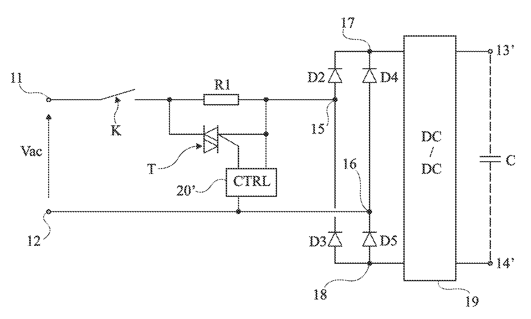
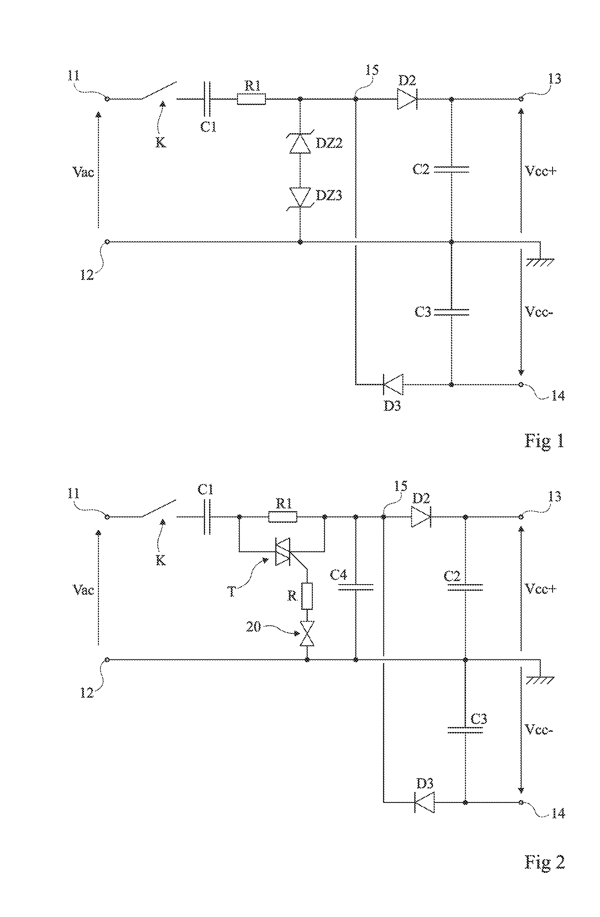
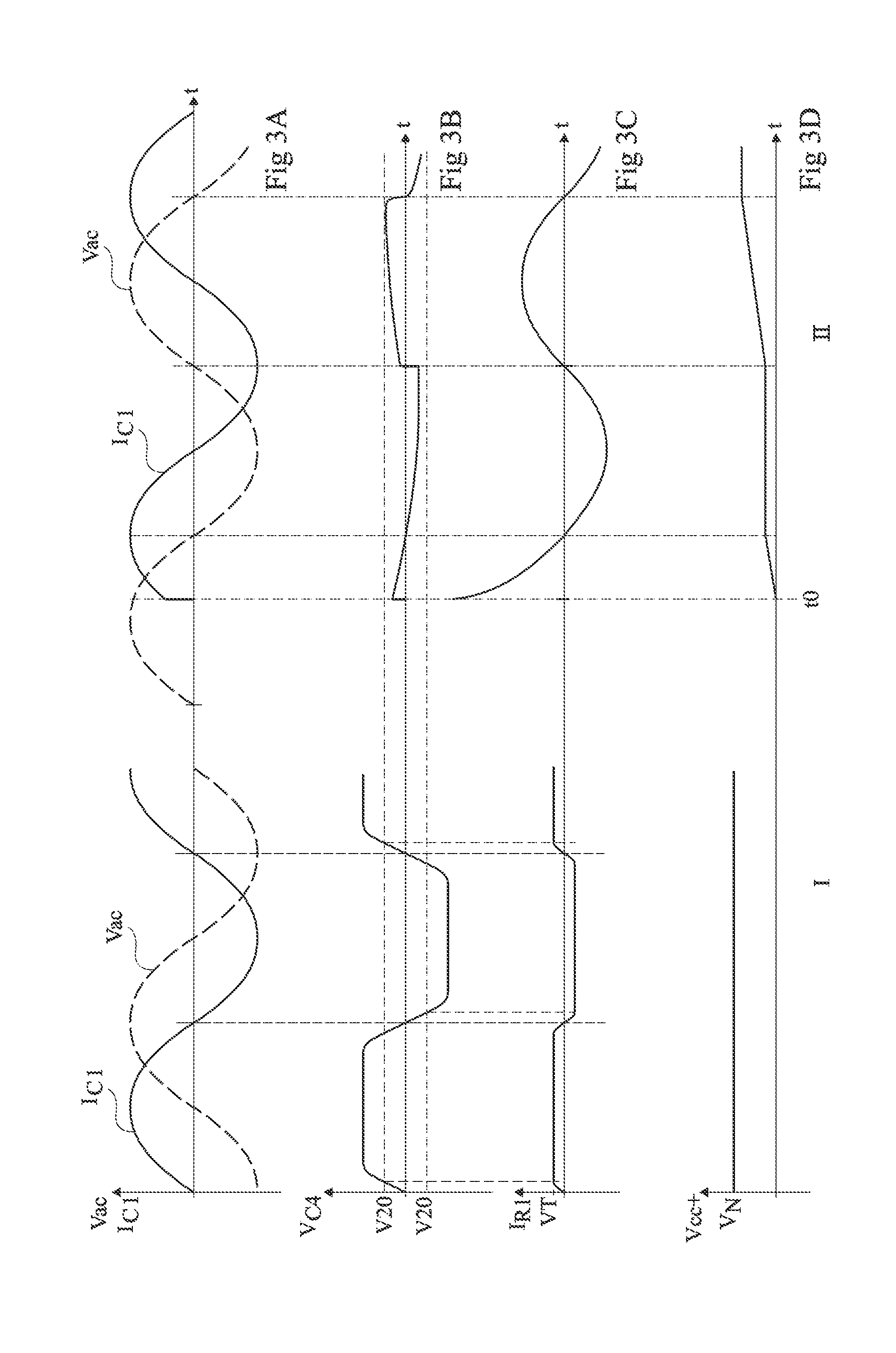
[0028]The same elements have been designated with the same reference numerals in the different drawings, and the timing diagrams have not been drawn to scale. For clarity, only those elements which are useful to the understanding of the embodiments have been shown and will be described. In particular, what exploitation is made of the voltages generated by the power supply circuit has not been detailed, the embodiments being compatible with usual applications.

[0029]FIG. 1 is an electric diagram of an embodiment of a capacitive power supply circuit. The example of FIG. 1 relates to a power supply intended to generate positive and negative D.C. voltages Vcc+ and Vcc−. The circuit is intended to be connected to two terminals 11 and 12 for applying an A.C. voltage Vac and is based on the use of a series capacitor C1 and of parallel capacitors C2 and C3 respectively assigned to the positive and negative power supply voltages. Capacitor C1 is connected, via a power switch K, to terminal 11...


PUM


Abstract

A capacitive power supply including: a first capacitive element and a first resistive element in series between a first terminal of a power switch and at least one rectifying element having a second terminal connected to a first electrode of at least one second capacitive element for providing a D.C. voltage; and a bidirectional switch in parallel on the resistor.

Description

CROSS REFERENCE TO RELATED APPLICATIONS[0001]This application claims the priority benefit of French patent application number 10 / 60712, filed on Dec. 17, 2010, entitled CAPACITIVE POWER SUPPLY WITH SURGE CURRENT LIMITATION, which is hereby incorporated by reference to the maximum extent allowable by law.BACKGROUND[0002]1. Technical Field[0003]Embodiments generally relate to electronic circuits and, more specifically, to circuits for generating D.C. voltages based on an A.C. voltage. Embodiments more specifically apply to capacitive power supplies and to diode bridge power supplies.[0004]2. Discussion of the Related Art[0005]Power supplies are widely used in electronics and are used to generate one or several D.C. power supply voltages from an A.C. voltage. Such power supplies are most often directly connected to the electric distribution mains via a power switch. As a result, the powering-on of the power supply circuit is not synchronized with the zero crossing of the A.C. power sup...

Claims


Application Information

Patent Timeline
IPC IPC(8): H02M7/06
CPCH02H9/001H02M7/125H02M7/062H02M7/05
Inventor GONTHIER, LAURENTPASSAL, ANTOINE
Owner STMICROELECTRONICS (TOURS) SAS
Learn More