Measuring transducer of vibration type and measuring system

a technology of measuring transducers and vibration types, applied in the direction of measuring devices, mass flow measurement devices, instruments, etc., can solve the problems of unavoidable increase in the empty mass of the measuring transducer, and achieve the effects of reducing the dissipation of oscillatory energy, reducing the accuracy of measurement, and increasing the oscillation quality factor

Active Publication Date: 2014-10-21
ENDRESS HAUSER FLOWTEC AG
View PDF5 Cites 25 Cited by
  • Summary
  • Abstract
  • Description
  • Claims
  • Application Information

AI Technical Summary

Benefits of technology

[0039]An advantage of the invention lies additionally in the fact that, among other things, due to the symmetry characteristics of the tube arrangement, transverse forces caused by bending oscillations of curved measuring tubes can largely be neutralized, transverse forces, which—as is, among other things, discussed in the previously mentioned EP-A 1 248 084 and U.S. Pat. No. 7,350,421—act essentially perpendicularly to the longitudinal section planes of the respective measuring transducer or its tube arrangement, and can be quite damaging for the accuracy of measurement of measuring transducers of vibration type. Additionally, in the case of measuring transducers of the aforementioned type, in comparison to conventional measuring transducers with only one or two bent measuring tubes, an increased oscillation quality factor of the measuring transducer as a whole could be detected, this not least of all also as a result of a significantly lessened dissipation of oscillatory energy from the measuring transducer into the pipeline connected thereto, for instance, as a result of actually undesired deformations of the flow dividers. Moreover, the oscillations of the measuring tubes of measuring transducers according to the present invention also exhibit—in comparison to conventional measuring transducers—a significantly lessened pressure jolt, or sound, dependence.
[0040]A further advantage of the measuring transducer of the invention is additionally also to be seen in the fact that predominantly established structural designs, such as concern, for instance, the materials used, the joining technology, the manufacturing steps, etc., can be applied or need only be modified slightly, whereby also manufacturing costs as a whole are quite comparable to conventional measuring transducers. In this respect, a further advantage of the invention is to be seen in the fact that not only is an opportunity created to implement comparatively compact measuring transducers of vibration type even with large nominal diameters of over 150 mm, especially with a nominal diameter of larger than 250 mm, with manageable geometric dimensions and empty masses, but these can also additionally be implemented in an economically sensible manner.
[0041]The measuring transducer of the invention is, consequently, especially suitable for measuring flowable media conveyed in a pipeline with a caliber of larger than 150 mm, especially of 300 mm or more. In addition, the measuring transducer is also suitable for measuring even mass flows, which are, at least at times, greater than 1000 t / h, especially, at least at times, greater than 1500 t / h, such as can occur, for example, in the case of applications for measuring petroleum, natural gas or other petrochemical materials.

Problems solved by technology

Associated therewith, the empty mass of the measuring transducer also increases unavoidably, wherein conventional measuring transducers of large nominal diameter are already implemented with an empty mass of, for instance, 400 kg.

Method used


Image

  • Measuring transducer of vibration type and measuring system
  • Measuring transducer of vibration type and measuring system
  • Measuring transducer of vibration type and measuring system

Examples


Embodiment Construction

[0051]While the invention is susceptible to various modifications and alternative forms, exemplary embodiments thereof have been shown by way of example in the drawings and will herein be described in detail. It should be understood, however, that there is no intent to limit the invention to the particular forms disclosed, but on the contrary, the intention is to cover all modifications, equivalents, and alternatives falling within the spirit and scope of the invention as defined by the intended claims.

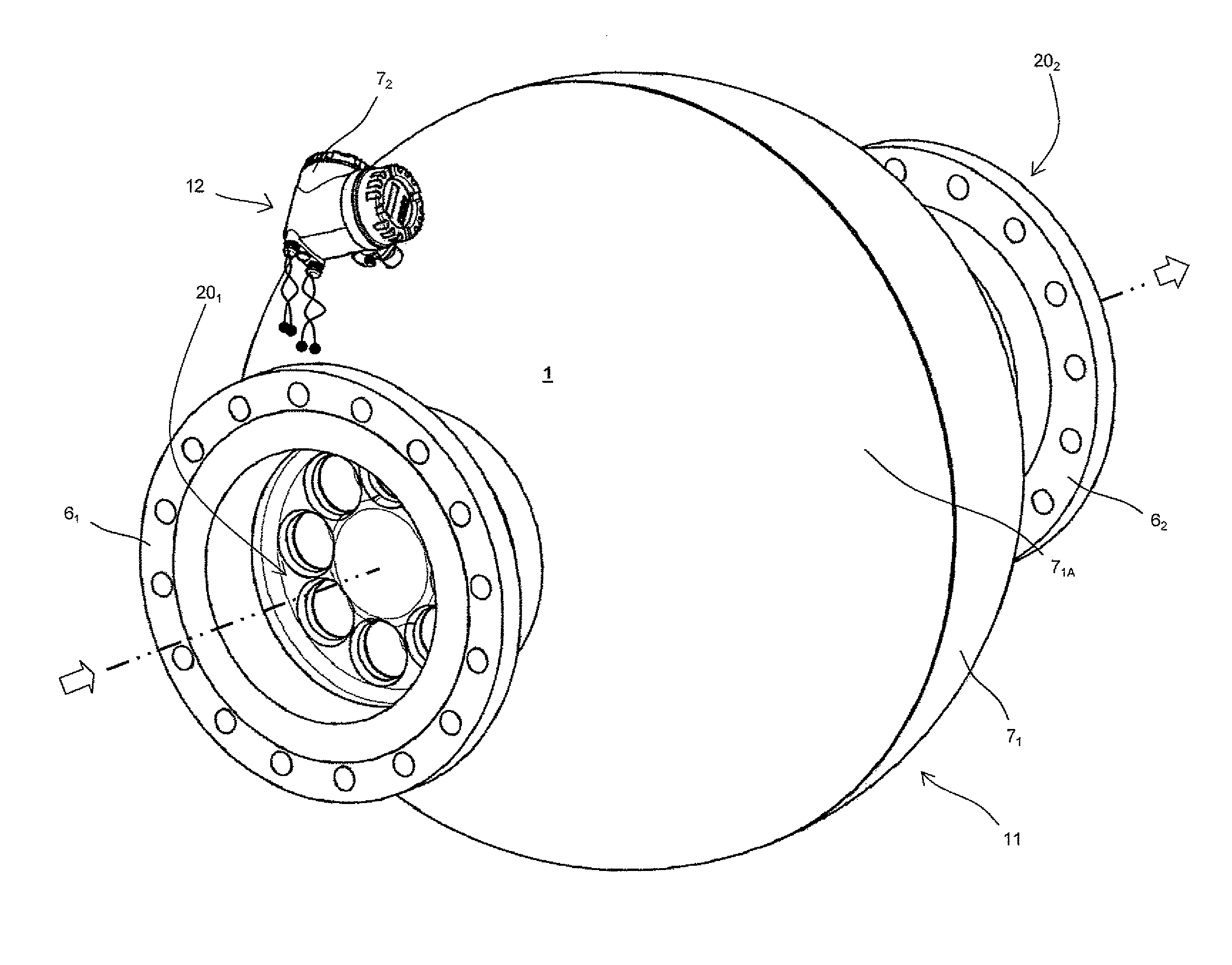
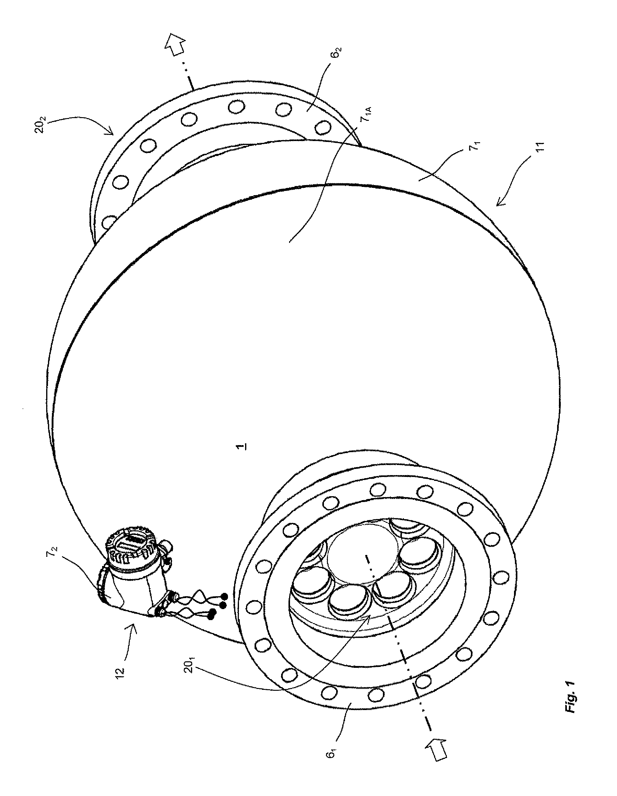
[0052]FIG. 1 shows schematically a measuring system 1, especially one embodied as a Coriolis mass flow, and / or density, measuring device, which not least of all serves to register a mass flow m of a medium flowing in a pipeline—not shown here for reasons of perspicuity—and to present this in a mass flow measured value instantaneously representing this mass flow. The medium can be practically any flowable material, for example, a powder, a liquid, a gas, a vapor or the like. Alternativ...


PUM


Abstract

A measuring transducer comprises a transducer housing, of which an inlet-side housing end is formed by means of an inlet-side flow divider having eight, mutually spaced flow openings and an outlet-side housing end is formed by means of an outlet-side flow divider having eight, mutually spaced flow openings as well as a tube arrangement with eight bent measuring tubes for the conveying flowing medium, which, forming flow paths connected for parallel flow, are connected to the flow dividers, wherein each of the eight measuring tubes in each case opens with an inlet-side measuring tube end into one of the flow openings of the flow divider, and in each case opens with an outlet-side measuring tube end into one of the flow openings of the flow divider. An electro-mechanical exciter mechanism of the measuring transducer serves for producing and / or maintaining mechanical oscillations of the measuring tubes.

Description

CROSS-REFERENCE TO RELATED APPLICATION[0001]This application is a Nonprovisional which claims the benefit of Provisional Application 61 / 481,301 filed on May 2, 2011.FIELD OF THE INVENTION[0002]The invention relates to a measuring transducer of vibration type for measuring a flowable medium conveyed in a pipeline, especially a medium in the form of a gas, a liquid, a powder or other flowable material, especially for measuring a density and / or a mass flow rate, especially also a total mass flow totaled over a time interval, of a medium flowing in a pipeline at least at times with a mass flow rate of more than 1000 t / h, especially more than 1500 t / h. Additionally, the invention relates to a measuring system with such a measuring transducer, for instance, one embodied as an in-line measuring device.BACKGROUND OF THE INVENTION[0003]In process measurements and automation technology, for measuring physical parameters—e.g. mass flow, density and / or viscosity—of media flowing in pipelines—fo...

Claims


Application Information

Patent Timeline
Patent Type & Authority Patents(United States)
IPC IPC(8): G01F1/84G01F15/00G01F15/14
CPCG01F1/8409G01F1/8477G01F15/14G01F1/8422G01F1/8413G01F1/8418G01F15/006G01F15/02
Inventor BITTO, ENNIOTSCHABOLD, PETERMUNDSCHIN, DIETERSCHUTZE, CHRISTIANANKLIN, MARTIN
Owner ENDRESS HAUSER FLOWTEC AG
Why Eureka
Try Eureka