Method and device to measure the velocity of a fluid flowing in a confined space

a fluid flow and velocity technology, applied in the direction of measurement devices, volume/mass flow measurement, instruments, etc., can solve the problems of important noise impairing the accuracy of measurement, and achieve the effect of reducing potential side lobe formation, reducing noise, and being non-invasiv

Pending Publication Date: 2022-01-13
FLOW TRONIC
View PDF0 Cites 0 Cited by
  • Summary
  • Abstract
  • Description
  • Claims
  • Application Information

AI Technical Summary

Benefits of technology

[0005]The present invention aims to provide an improved non-invasive method and device for measuring the velocity of a fluid flowing in a confined space such as a sewer or an underground channel, using a patch antenna as microwave transmitter and receiver. To this end, at least the transmitting area of the patch antenna is mounted at one end of a reflector tube. The other end of the tube is left open or equipped with a microwave lens. This device with the reflector tube allows to encapsulate the side lobes of the microwave pattern (FIG. 13b) and redirect them towards the portion of the fluid that requires to be illuminated for the flow velocity measurement. The reduction of the side lobes allows to prevent their reflection of the walls of the pipe or channel, such a reflection resulting in an important noise impairing the accuracy of the measurement. Optionally, as aforementioned, the other open end may be equipped with a microwave lens. This lens could reduce potential side lobes formed at the exit of the reflector tube.
[0006]The reflector tube has a constant cross section over its length or a cross section expanding gradually over its length. This geometry allows to reduce or even annihilate the side lobes but does not affect significantly the directivity of the signal.

Problems solved by technology

The reduction of the side lobes allows to prevent their reflection of the walls of the pipe or channel, such a reflection resulting in an important noise impairing the accuracy of the measurement.

Method used


Image

  • Method and device to measure the velocity of a fluid flowing in a confined space
  • Method and device to measure the velocity of a fluid flowing in a confined space
  • Method and device to measure the velocity of a fluid flowing in a confined space

Examples


Embodiment Construction

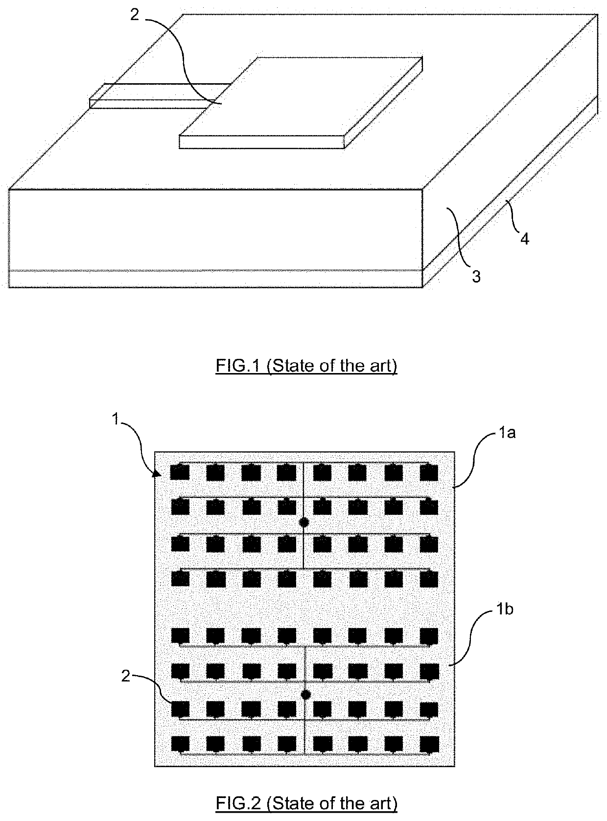
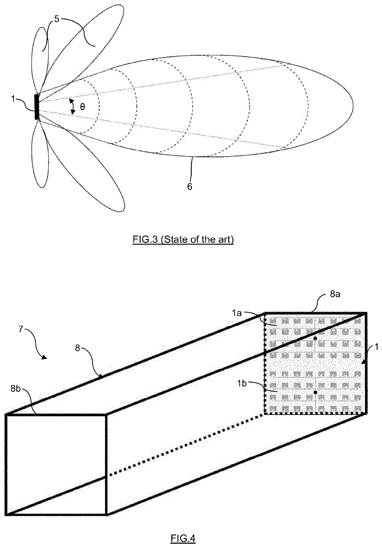
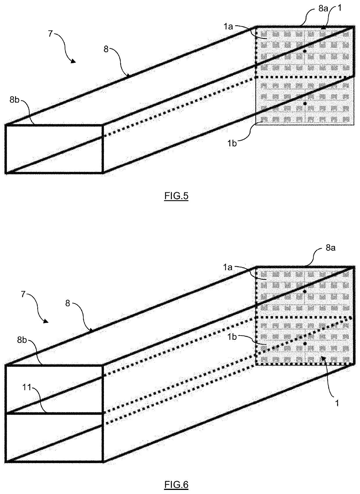
[0013]The invention relates to a non-invasive method and a device for measuring the surface velocity of a fluid flowing more specifically in a confined space. However, the present invention does not exclude to use this device for measurements in open air for rivers, irrigation channels and other large man-made channels. The device 7 comprises a patch antenna 1 with a set of interconnected patches acting as a microwave transmitter 1a and another set of interconnected patches acting as a microwave receiver 1b (FIG. 4-10). As shown in FIG. 4 or 5, at least the set of patches acting as the transmitter 1a is mounted at one end 8a of a reflector tube 8. This tube is electrically conductive and for example in metal. The other end 8b of the reflector tube 8 is left open or might be equipped with a microwave lens 9 as illustrated in FIG. 12. The transmitted microwave signal is guided through this electrically conductive tubular shaped volume to the surface of the fluid 10 as represented in F...


PUM


Abstract

The invention relates to a device (7) for measuring the surface velocity of a fluid (10) flowing in a confined space such as through a pipe or a channel (12), said device (7) comprising a patch antenna (1) with a transmitting area (1a) generating a microwave signal and a receiving area (1b) receiving the microwave signal reflected on the surface of the fluid (10), the device (7) being wherein it comprises an electrically conductive tube (8), called reflector tube, with at least the transmitting area (1a) of the patch antenna (1) mounted at one end (8a) of the reflector tube (8) to reduce the side lobes of the generated microwave signal. The invention also relates to the non-invasive method for measuring the surface velocity of the fluid using said device (7).

Description

FIELD OF THE INVENTION[0001]The invention relates to a method and device to measure the surface velocity of a fluid flowing in a confined space. More specifically, the present invention relates to a non-invasive method and device with a modified microwave patch antenna.BACKGROUND OF THE INVENTION[0002]Non-invasive methods for measuring the flow velocity of a fluid in a channel or sewer, i.e. methods wherein there is no contact between the probe and the fluid, are becoming more and more popular. Among the techniques used we can find acoustic methods, optical methods, laser methods and microwave methods, the last one being the most popular.[0003]Most sewer pipes and channels as well as most industrial waste water channels are located underground and consequently are in confined space. The non-invasive microwave technology is ideal to measure the fluid velocity in those applications. Microwave signals can be generated in different ways. Pulsed radars with horn antennas were historicall...

Claims


Application Information

Patent Timeline
Patent Type & Authority Applications(United States)
IPC IPC(8): G01F1/66
CPCG01F1/663G01F1/662G01F1/002
Inventor SEVAR, JEAN-MARIE
Owner FLOW TRONIC
Why Eureka
Try Eureka