Water cyclone with improved base pipe and overflows structure

A technology for hydrocyclones and overflow pipes, which is applied in the direction of swirl devices and devices in which the axial direction of the swirl can be reversed, etc., which can solve the problem of reducing the space under the cone of the cyclone and increasing the energy consumption of the cyclone , Reduce the separation efficiency of the cyclone, etc., to achieve the effects of reducing energy consumption, increasing the effective working space, and improving separation efficiency and output

Inactive Publication Date: 2008-09-03
EAST CHINA UNIV OF SCI & TECH
View PDF2 Cites 25 Cited by
  • Summary
  • Abstract
  • Description
  • Claims
  • Application Information

AI Technical Summary

Problems solved by technology

[0004] (1) Since the lower part of the hydrocyclone is a tapered cone, the denser components that move downward and are separated by centrifugation, and the lower density components that move upward along the center line are close to the outlet of the bottom flow port. It is easy to back-mix near the small end of the cone, so that some of the separated components are back-mixed together, which reduces the separation efficiency of the cyclone
[0005] (2) Especially when the inlet solution contains dissolved air, due to the separation effect of the centrifugal swirl, the dissolved gas is precipitated and surrounds the central axis with lower pressure and cannot be discharged
[0006] (3) A small part of the fluid (accounting for 10-20% of the total amount of imported materials) will go down the outer wall of the overflow pipe to the overflow port and be discharged directly from the overflow port. It is usually called short-circuit flow, and the short-circuit flow is directly discharged without separation. , which seriously reduces the separation efficiency of the cyclone
However, it has been found that since the air column is sealed inside the cyclone and cannot be drained away, the volume of the central column makes the air column expand outwards, further reducing the space in the lower part of the cyclone cone, which in turn aggravates the back-mixing phenomenon and further reduces The separation efficiency of the cyclone
[0010] (2) The central column is prone to vibration and even breakage during operation
[0011] (3) The spiral blades on the overflow pipe, the lower blades are beneficial to reduce short-circuit flow, while the spiral blades on the upper part of the overflow pipe have no effect on preventing short-circuit flow, but will increase the energy consumption of the cyclone operation

Method used


Image

  • Water cyclone with improved base pipe and overflows structure
  • Water cyclone with improved base pipe and overflows structure

Examples


Embodiment Construction

[0030] The present invention can be further understood through the following examples, but the content of the present invention cannot be limited.

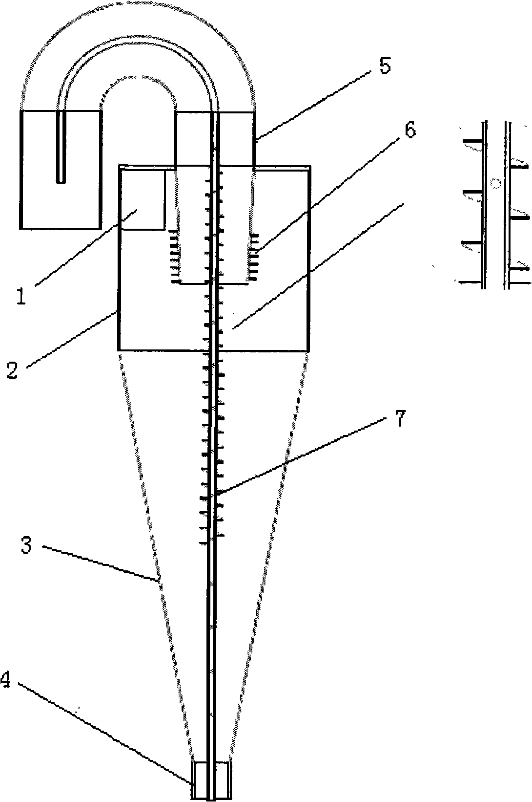
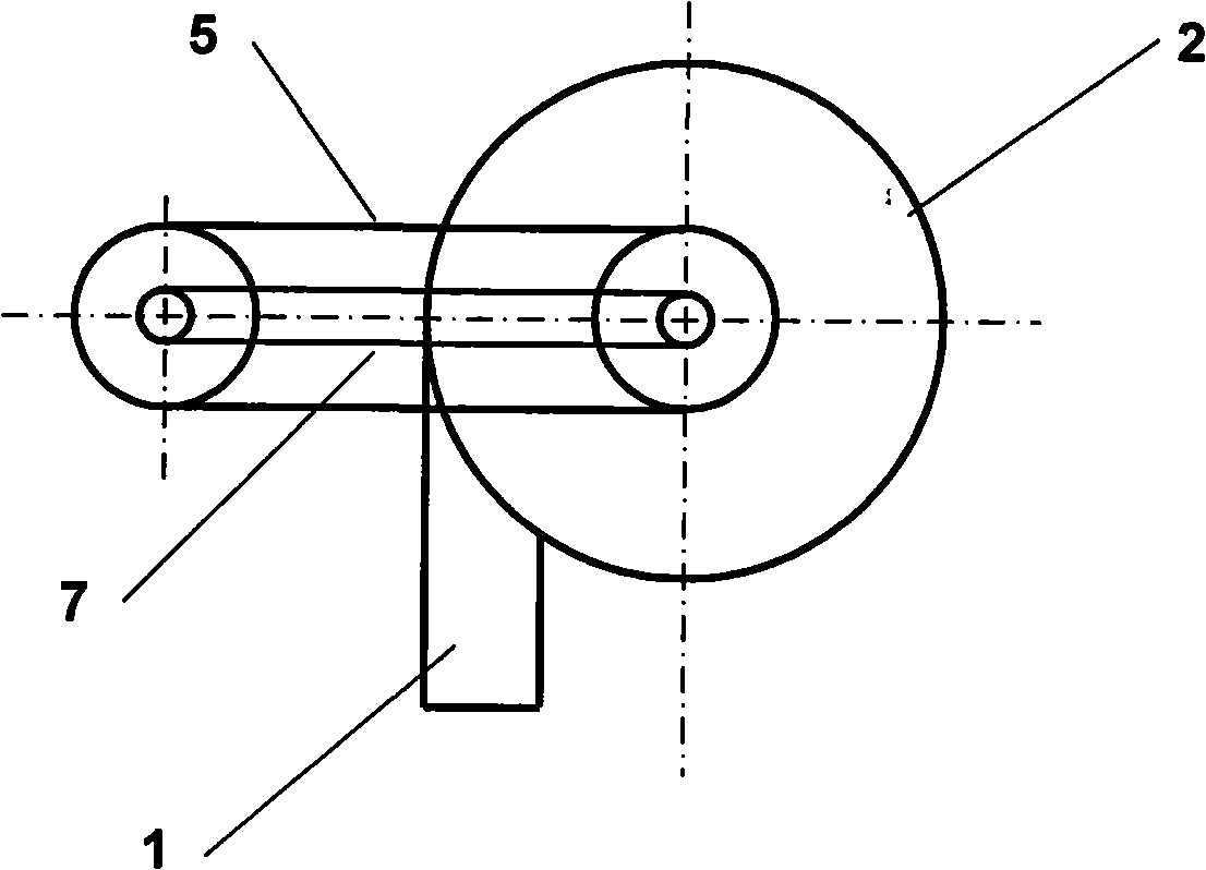
[0031] as attached figure 1 and 2 As shown, the utility cyclone consists of a feed pipe 1, a cylindrical section 2 of the cyclone, a conical section 3 of the cyclone, an underflow pipe 4, an overflow pipe 5, a spiral fin 6 at the lower part of the overflow pipe, The central column with the helical guide vanes is composed of 7. The central column is a hollow pipe with several small exhaust holes on it. The diameter of the exhaust holes can be 3 to 5 mm for small cyclones and about 5 to 20 in number. The diameter of exhaust holes for large cyclones , can be 5~10mm, and the number can be about 10~50. So that the air column precipitated during the swirl operation can enter the center pipe and be taken away by the negative pressure generated by the flow rate of the overflow liquid discharged from the overflow pipe. Too many vent h...


PUM


Abstract

The invention belongs to a device for solid-liquid separation/classification and non-homogeneous separation, specifically a hydraulic cyclone with improved structure of central post and overflow pipe. The device comprises a feed pipe, a cylindrical section, a coniform section, an overflow pipe and a hollow tubular central post with partial-spiral fins and spiral flow deflectors and provided outside the overflow pipe. The central post is a hollow tube provided thereon with a plurality of holes. The spiral flow deflectors are provided on the outer surface of the central post. The spiral fins are provided on the overflow pipe from the bottom of the overflow pipe to a height below the bottom of an inlet pipe. Compared with the prior art, the separation efficiency of the hydraulic cyclone is increased by 5-10% and the energy consumption is reduced by 20%. The hydraulic cyclone has high stability and reliability in separation efficiency and is suitable for solid-liquid separation in ore dressing, dredging, chemical and petroleum industries.

Description

technical field [0001] The invention belongs to a device for solid-liquid separation, classification and heterogeneous separation, in particular to a hydrocyclone. Background technique [0002] At present, the hydrocyclone consists of a cylindrical section, a conical section, an overflow port, an underflow port and a feed port. The overflow port is connected with the top cover at the upper end of the cylinder, and the feed port enters the cylinder cavity along the tangential direction of the side at the upper part of the cylinder. The mixed material enters the hydrocyclone along the tangential direction, and the fluid forms a high-speed rotating flow field in the cylindrical cavity. It moves downward in the axial direction, and when it reaches the cone section, it continues to move downward along the wall of the vessel and is discharged from the underflow port, thus forming an external swirling flow, and the components with low density move towards the central axis, and in ...

Claims


Application Information

Patent Timeline
Patent Type & Authority Applications(China)
IPC IPC(8): B04C5/107B04C5/12B04C5/103
Inventor 潘家祯赵天彪周先桃石岩
Owner EAST CHINA UNIV OF SCI & TECH
Why Eureka
Try Eureka