

Decorative part, timepiece, and manufacturing method of decorative part
- Summary
- Abstract
- Description
- Claims
- Application Information
AI Technical Summary
Benefits of technology
Problems solved by technology
Method used
Image


Examples
first embodiment
Modification of First Embodiment
[0079]FIGS. 7A to 7D are explanatory views illustrating the manufacturing method of the body of the oscillating weight and the weight, and FIGS. 7A to 7D illustrate each process. Moreover, in the description below, since the fixing member mounting process in which the screws 61 are inserted into the through-holes 164a of the body 164 of the oscillating weight and the smooth surface forming process in which one surface 164b of the body 164 of the oscillating weight and the head portions 61a of the screws 61 are smoothed are similar to those of the above-described first embodiment, the description is omitted.
[0080]Here, two processes of a first anodizing process and a second anodizing process are performed on the body 164 of the oscillating weight and the screws 61.
[0081]That is, first, as illustrated in FIG. 7A, a first anodizing process is preformed on the body 164 of the oscillating weight and the screws 61 that have undergone the smooth surface form...
second embodiment
[0087]Next, a second embodiment of the invention will be described based on FIG. 8 while referring to the FIGS. 1 and 2. In addition, the same reference numbers are denoted to parts similar to those of the first embodiment and described (similarly applied also to embodiments hereinafter).
[0088]FIG. 8 is a longitudinal cross-section illustrating an oscillating weight according to the second embodiment.
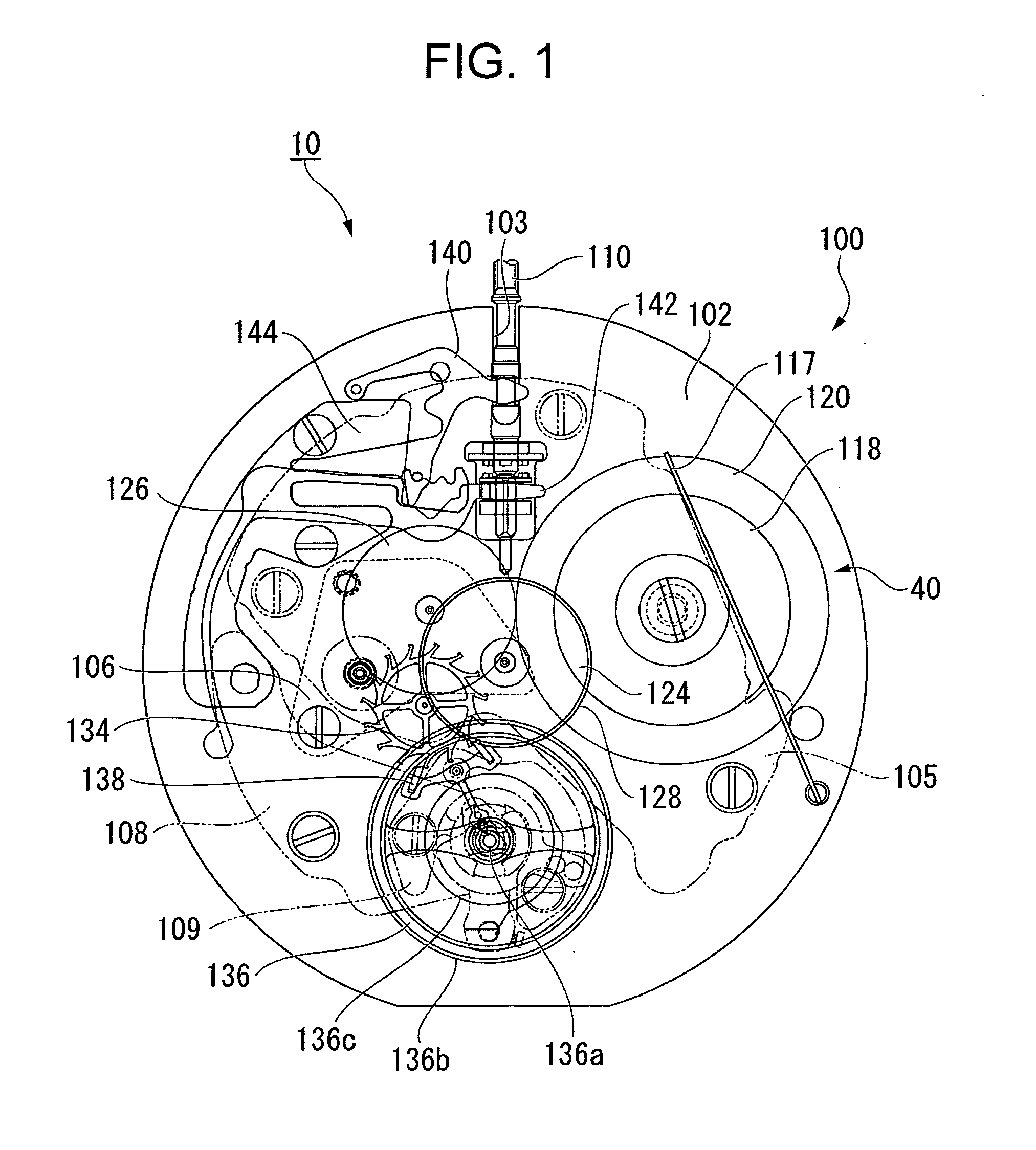
[0089]In the second embodiment, basic configurations such as the configuration in which the automatic winding watch 10 includes the movement 100, and the train wheel referred to as the front train wheel, and the escapement and regulating device 40 for controlling the rotation of the front train wheel, the automatic winding mechanism 60, or the like are built into the front side of the movement 100, the configuration in which the oscillating weight 260 of the automatic winding mechanism 60 includes ball bearings 162, the body 164 of the oscillating weight, and the weight 266, and the bod...
third embodiment
[0093]Next, a third embodiment of the invention will be described based on FIGS. 9 and 10.
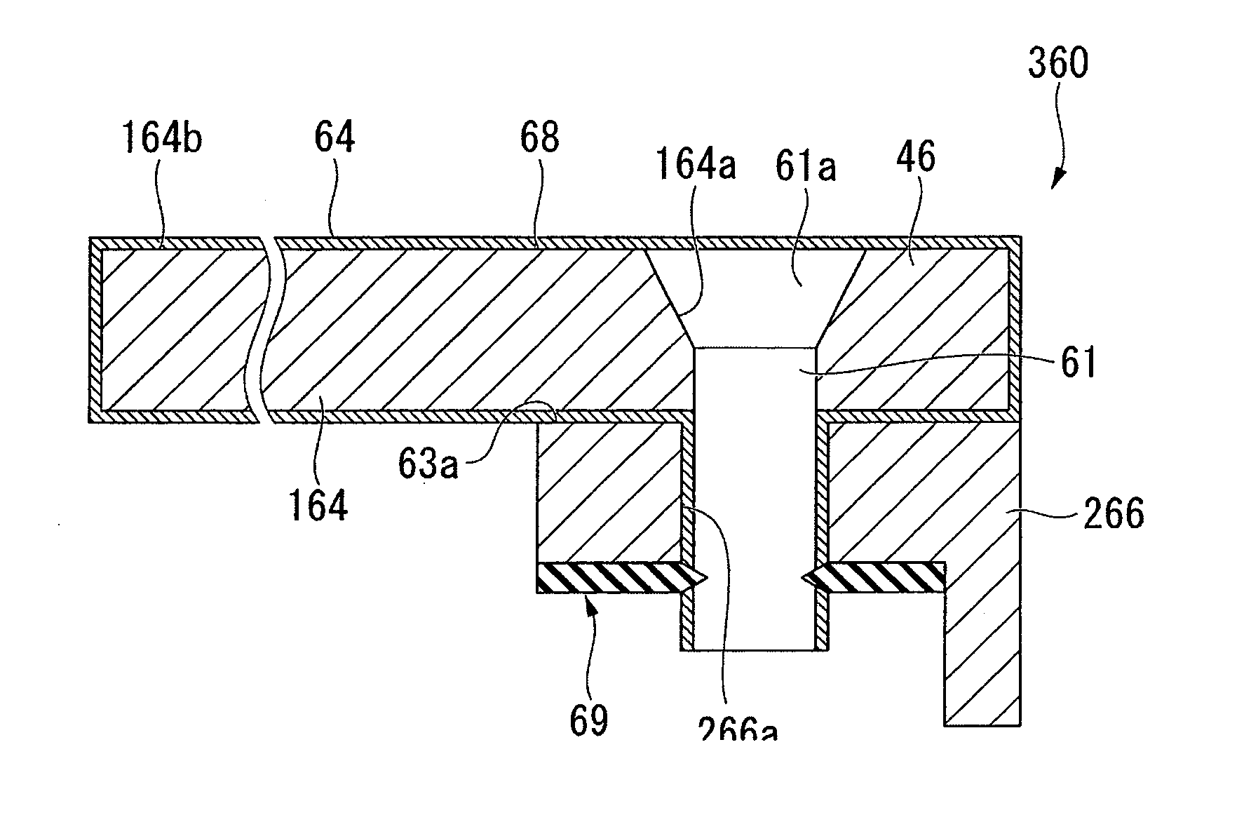
[0094]FIG. 9 is a longitudinal cross-sectional view illustrating an oscillating weight according to the third embodiment.
[0095]As illustrated in FIG. 9, the difference between the third embodiment and the above-described second embodiment is that the fixing methods of the body 164 of the oscillating weight with respect to the weight 266 are different from each other. That is, the oscillating weight 360 includes the body 164 of the oscillating weight and the weight 266, and the body 164 of the oscillating weight and the weight 266 are fixed to each other by the screws 61 which is inserted into the through-holes 164a of the body 164 of the oscillating weights and the through-holes 266a of the weight 266 and a C-type snap ring 69 which can be engaged to the screws 61.
[0096]FIG. 10 is a plan view illustrating the C-type snap ring.
[0097]As illustrated in FIG. 10, in the C-type snap ring 69, a C-shap...
PUM
| Property | Measurement | Unit |
|---|---|---|
| Weight | aaaaa | aaaaa |
Abstract
Description
Claims
Application Information