

A quadrature compensation method for MEMS gyroscopes and a gyroscope sensor
- Summary
- Abstract
- Description
- Claims
- Application Information
AI Technical Summary
Benefits of technology
Problems solved by technology
Method used
Image

Examples
Embodiment Construction
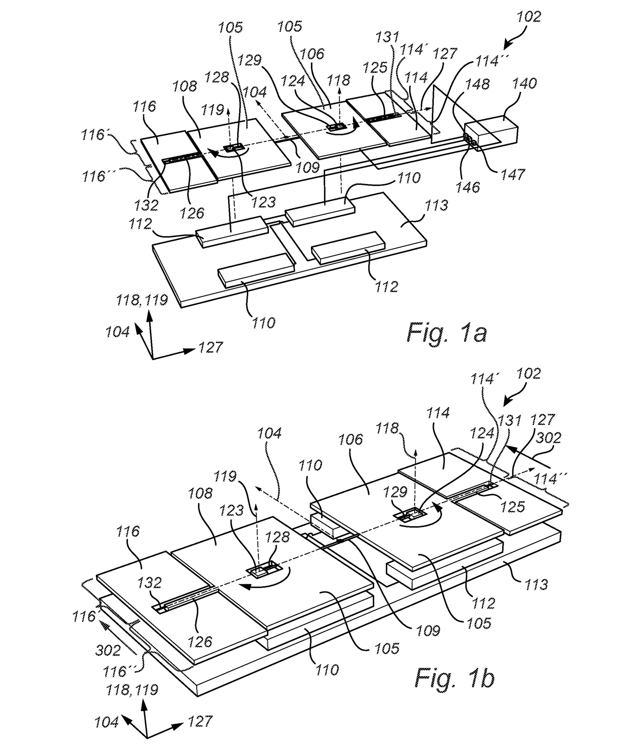
[0062]FIG. 1a illustrates an exploded view of a gyroscope sensor 102 and FIG. 1b illustrates a perspective view of the gyroscope sensor 102 shown in FIG. 1a, with the purpose of describing the basic principle of operation and the structural features of the gyroscope sensor 102. There is further an electronic device 140 electrically connected to the gyroscope sensor 102.
[0063]The gyroscope sensor 102 comprises a first 106 and a second 108 inertial mass, a first 110 and a second electrode 112, and total drive frames 114, 116, each total drive frame comprising a first 114′, 116′ and a second 114″, 116″ drive frame. There is also indicated in FIG. 1a-b, a sensitivity axis 104, excitation axes 118,119, and a detection axis 127 for the gyroscope sensor 102. The coordinate axes illustrates the orientation of the different axes 104, 118, 119, 127. The first 106 and the second 108 inertial mass are physically attached to each other via the connecting member 109. The connecting member 109 may...
PUM
 Abstract
Description
Claims
Application Information