Brushless motor control device and diagnostic processing method for same

Active Publication Date: 2017-04-27
PANASONIC INTELLECTUAL PROPERTY MANAGEMENT CO LTD
View PDF0 Cites 2 Cited by
  • Summary
  • Abstract
  • Description
  • Claims
  • Application Information

AI Technical Summary

Benefits of technology

The present invention prevents errors in the speed and torque of a cooling fan caused by abnormal conditions in the AD converter circuits, clock generation circuit, or current detection circuit. This results in a more stable airflow and reduced driving sound from the cooling fan. This invention allows for the use of a smaller motor, reducing size and weight of the cooling fan. It also uses a small microcomputer and inexpensive circuit configuration, instead of adding complex diagnostic circuits, which limits costs.

Problems solved by technology

With this configuration, if there is an error in a current detection circuit for detecting values of currents flowing through the coils, an analog-digital (AD) converter circuit for enabling an output from the current detection circuit to be input to a microcomputer, or a clock generation circuit for generating an unit of time, an error also occurs in a calculated actual rotational speed and calculated torque, resulting in differences between the actual rotational speed and the torque and target values.
However, the conventional configuration, which can determine whether the clock generation circuit is in an abnormal condition, cannot determine whether a current detection circuit and an AD converter circuit are in an abnormal condition.
Therefore, the method cannot prevent increased errors in a rotational speed and torque due to an abnormal condition of the AD converter circuit and the current detection circuit, and thus cannot prevent increased variations in an airflow of a cooling fan and a driving sound emitted by the cooling fan.
This, however, requires a large microcomputer because a small microcomputer, which has fewer pins, cannot achieve a circuit configuration, resulting in increased cost.

Method used


Image

  • Brushless motor control device and diagnostic processing method for same
  • Brushless motor control device and diagnostic processing method for same
  • Brushless motor control device and diagnostic processing method for same

Examples


Embodiment Construction

[0016]An exemplary embodiment of the present invention is described below with reference to the accompanying drawings.

Exemplary Embodiment

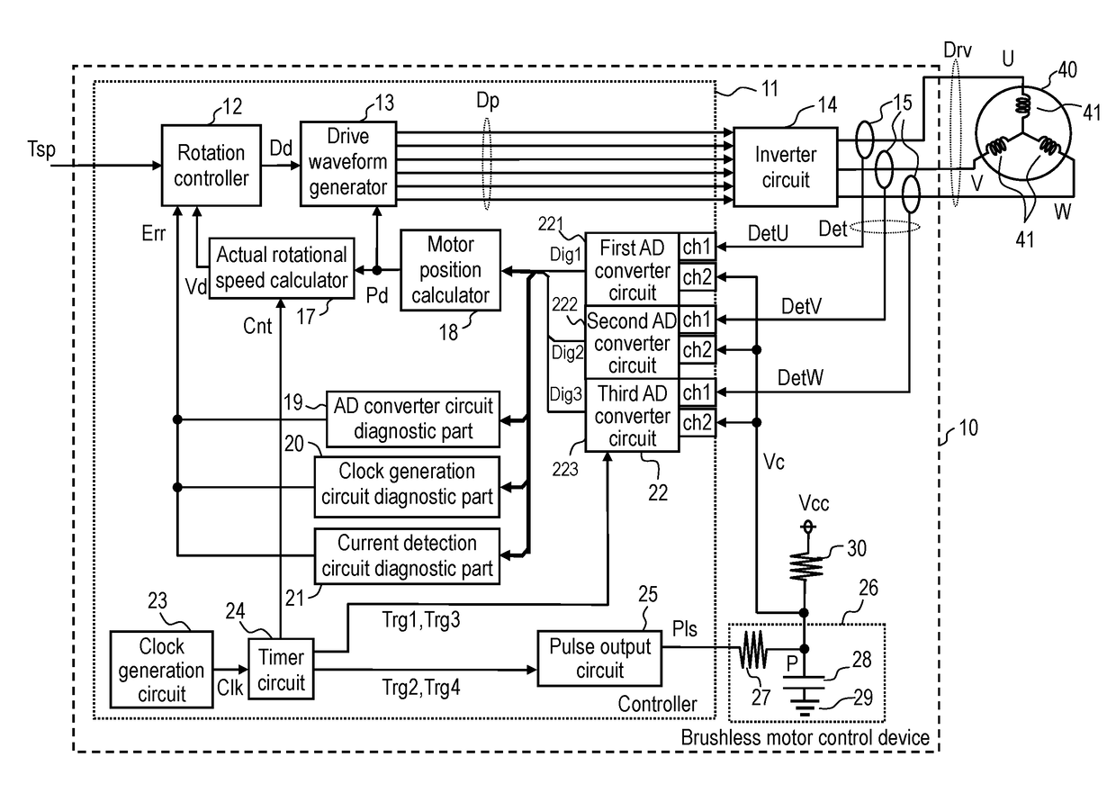
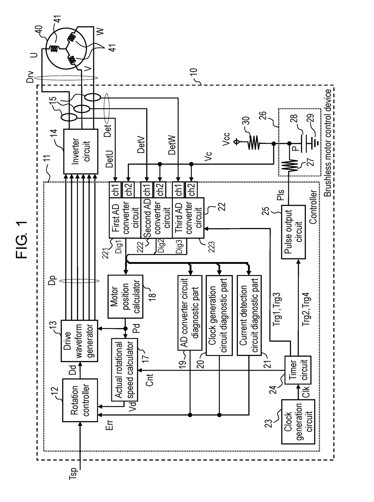
[0017]FIG. 1 is a block diagram illustrating a configuration of brushless motor control device 10 according to the exemplary embodiment of the present invention. FIG. 1 illustrates an example configuration of brushless motor control device 10 according to the present exemplary embodiment, with brushless motor 40 connected to brushless motor control device 10. With this configuration, brushless motor control device 10 controls driving of brushless motor 40 so that brushless motor 40 rotates according to an external command.

[0018]Brushless motor 40 includes a stator having coils 41 each formed by winding a wire around a stator core, and a rotor which rotates about a shaft when coils 41 are being energized to drive. In the present exemplary embodiment, a description is given of an example in which brushless motor 40 includes coils 41 in three phases ...


PUM


Abstract

The brushless motor control device according to the present invention includes a drive controller, current detection circuits, AD converter circuits, a clock generation circuit, a pulse output circuit, and an RC filter. The drive controller generates a driving signal for driving a brushless motor. The current detection circuits each detect a current of the brushless motor. The AD converter circuits are each connected to a different one of the current detection circuits. The clock generation circuit outputs a clock pulse. The pulse output circuit outputs a pulse signal according to the clock pulse. The RC filter receives the pulse signal. The RC filter is formed of a resistor and a capacitor connected in series. A pull-up resistor connecting to a predetermined power supply is connected to an intermediate connection point between the resistor and the capacitor. The intermediate connection point is connected to the AD converter circuits. Based on output values form the AD converter circuits, it is determined whether the clock generation circuit, the AD converter circuits, and the current detection circuit are in an abnormal condition.

Description

TECHNICAL FIELD[0001]The present invention relates to a brushless motor control device for driving and controlling a brushless motor and a diagnostic processing method for the brushless motor control device. More particularly, the present invention relates to a brushless motor control device capable of diagnosing circuits of a motor control circuit that when in an abnormal condition cause errors in a rotational speed and torque to increase relative to a command so that the errors are prevented from increasing, and to a diagnostic processing method for the brushless motor control device.BACKGROUND ART[0002]In recent years, a brushless motor is used in a cooling fan commonly used for, for example, a refrigerator, because the brushless motor is long-life and meets a demand for energy efficiency. Such a cooling fan needs to be controlled to satisfy, for example, required airflows and driving sounds emitted in its surrounding area, which are preset values corresponding to air temperature...

Claims


Application Information

Patent Timeline
IPC IPC(8): H02P6/12H02P3/18H02P27/08
CPCH02P6/12H02P3/18H02P27/08H02P6/18H02P29/0241H02M1/0025
Inventor SATO, DAISUKE
Owner PANASONIC INTELLECTUAL PROPERTY MANAGEMENT CO LTD
Why Eureka
Try Eureka