
Device and method for measuring the flow of a fluid in a tube moved by a peristaltic pump

Pending Publication Date: 2022-05-12
STMICROELECTRONICS SRL
View PDF0 Cites 0 Cited by
  • Summary
  • Abstract
  • Description
  • Claims
  • Application Information

AI Technical Summary

Benefits of technology

The patent application provides a way to measure the flow of a fluid in a tube, especially when it is moved by a peristaltic pump. The solution solves issues with current methods and allows for accurate detection of low flow rates with limited expense and space.

Problems solved by technology

In general, the aforementioned flowmeters are rather expensive devices, utilize sophisticated electronics with high energy consumption solutions and also have a size that does not allow miniaturization and thus their application where there is not enough space for installation.
In these applications, the measurement of flows even at very low flow rates, for example in the order of a few units or tens of ml per minute, may also be desired, for which common commercial solutions cannot find suitable application.

Method used


Image

  • Device and method for measuring the flow of a fluid in a tube moved by a peristaltic pump
  • Device and method for measuring the flow of a fluid in a tube moved by a peristaltic pump
  • Device and method for measuring the flow of a fluid in a tube moved by a peristaltic pump

Examples


Embodiment Construction

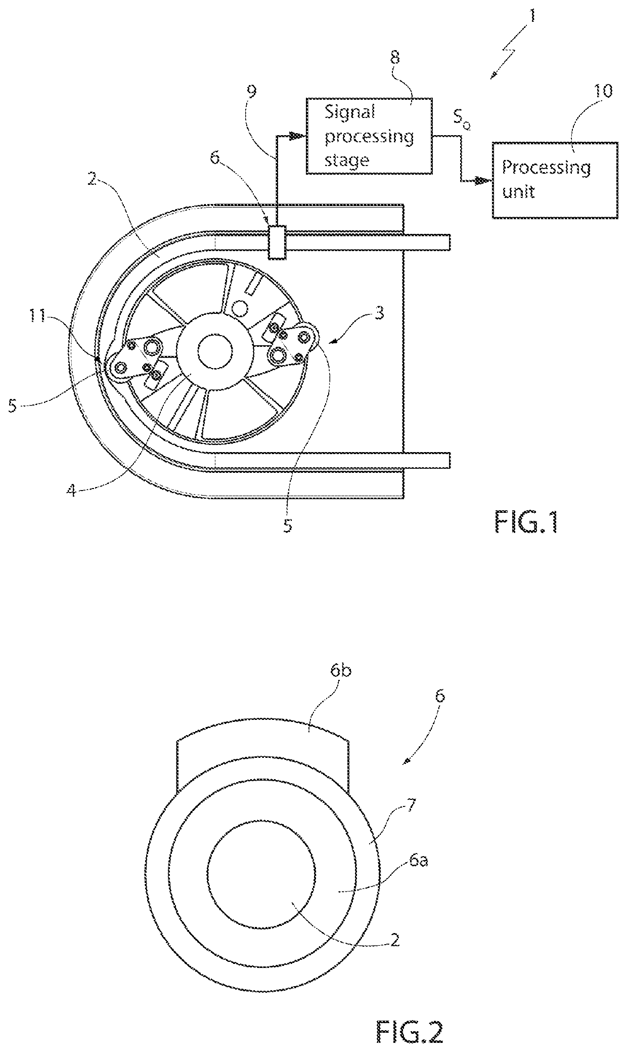
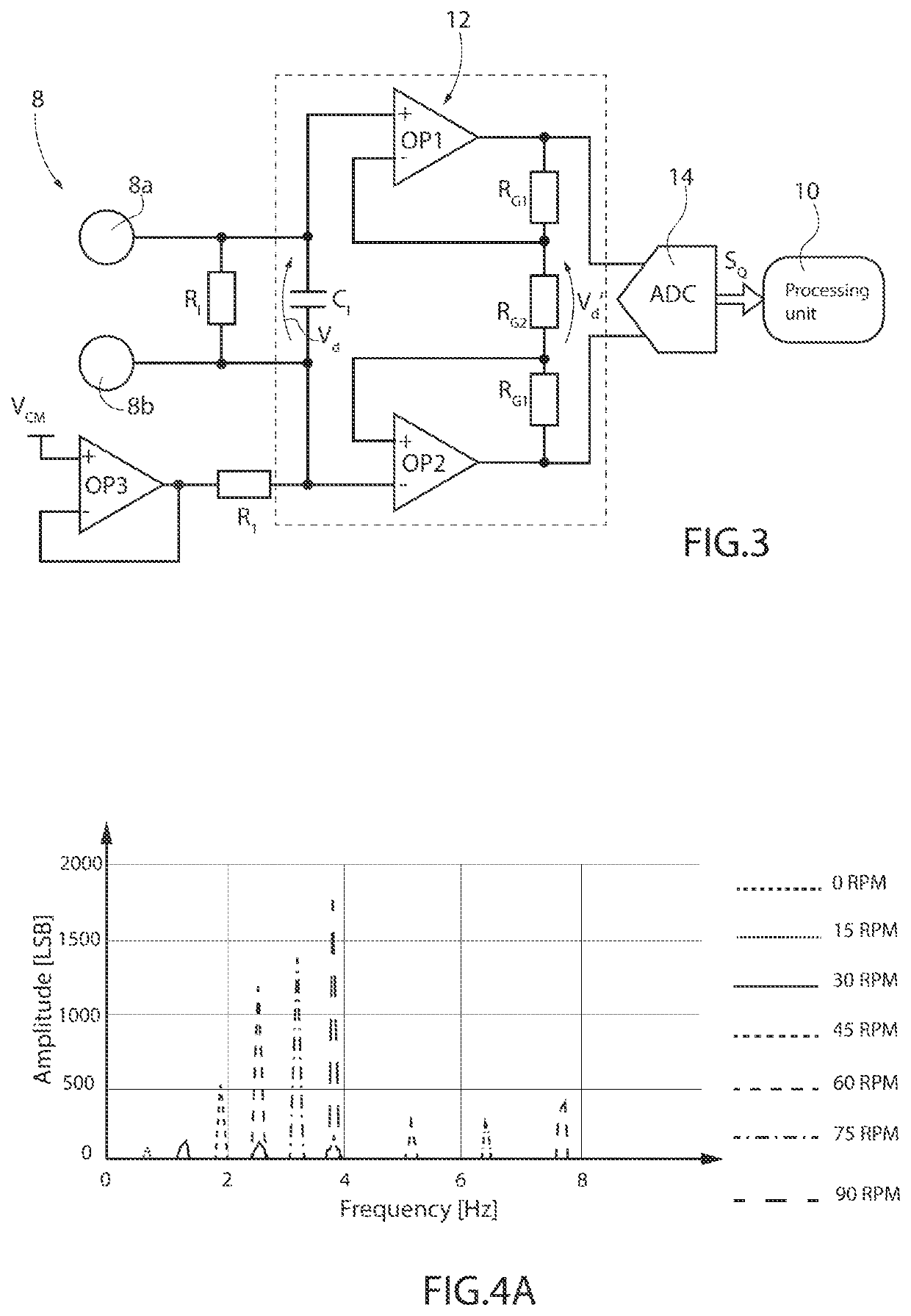
[0022]As will be described in detail hereinafter, an aspect of the present solution envisages, for measuring the flow of a fluid inside a tube moved by a peristaltic pump, a measuring device based on the use of an electrostatic charge variation sensor and on the processing of a charge variation signal detected by this sensor.

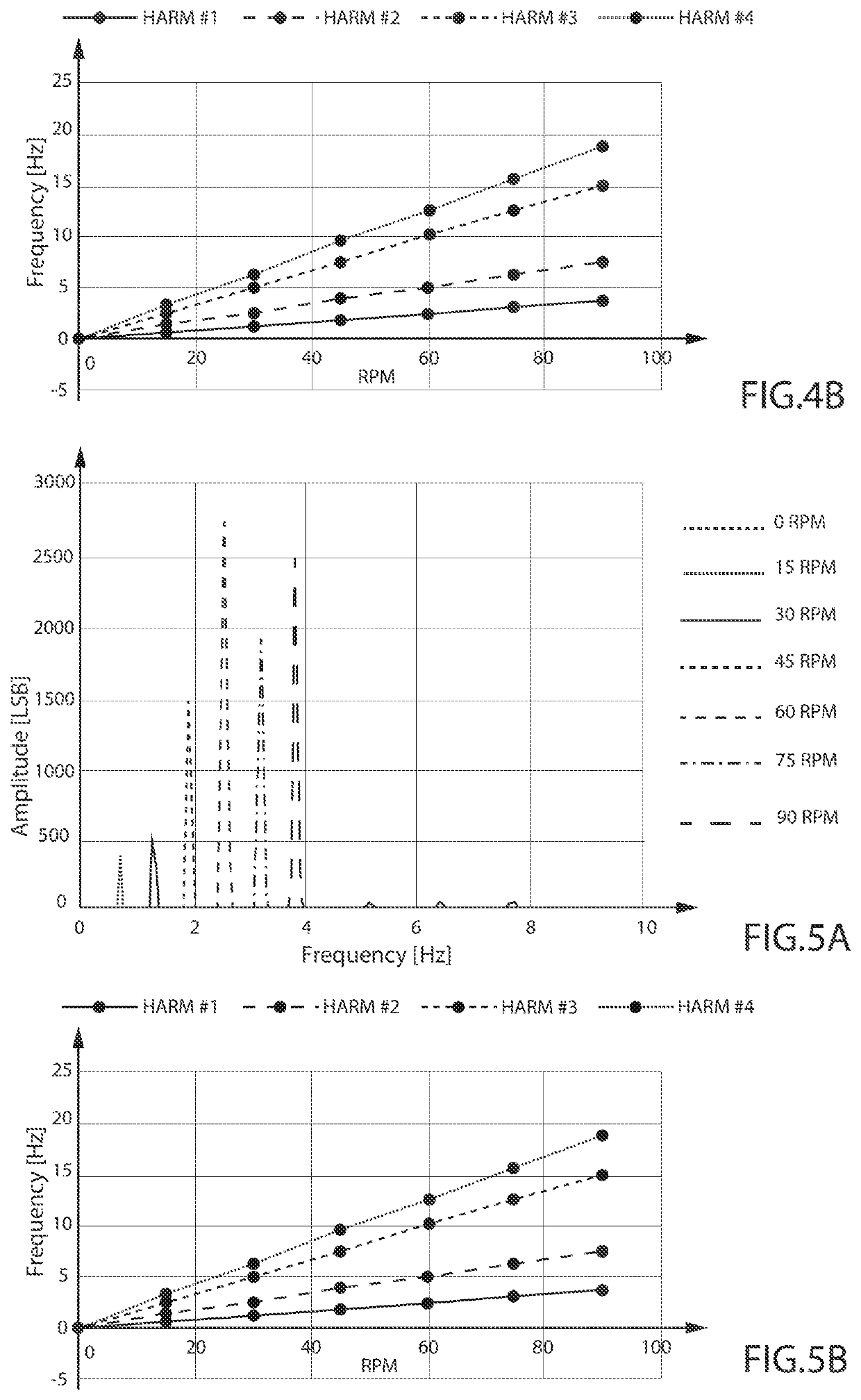
[0023]In proximity to the contact (or “friction”) area on which the roller elements of the peristaltic pump act, electrostatic charges are generated on the surface of the duct or tube due to the triboelectric effect. In detail, the electrostatic charge is generated on the inner walls of the tube due to the continuous compression and decompression of the same tube due to pinching by the roller elements of the peristaltic pump and to the subsequent release. At a generic time (t), due to the rotation of the rotor, a tube portion is compressed; at the immediately following time (t+1) the rotor shifts its compression action to the following section of the tube, causi...


PUM


Abstract

Various embodiments provide a device for measuring the flow of fluid inside a tube moved by a peristaltic pump is provided with: a detection electrode arrangement coupled to the tube to detect an electrostatic charge variation originated by the mechanical action of the peristaltic pump on the tube; a signal processing stage, electrically coupled to the detection electrode arrangement to generate an electrical charge variation signal; and a processing unit, coupled to the signal processing stage to receive and process in the frequency domain the electrical charge variation signal to obtain information on the flow of a fluid that flows through the tube based on the analysis of frequency characteristics of the electrical charge variation signal.

Description

BACKGROUNDTechnical Field[0001]The present solution relates to a device and a method for measuring the flow of a fluid in a tube, in particular the fluid being moved by a peristaltic pump.Description of the Related Art[0002]Devices for measuring the flow of a fluid inside a duct or tube (so-called flowmeters) based on various measurement techniques or principles are known; for example, electromagnetic, infrared, ultrasonic flowmeters, or flowmeters based on the use of pressure sensors are known.[0003]For example, the operating principle of an electromagnetic flowmeter is based on the Faraday's law of electromagnetic induction. When a conductive fluid flows through a magnetic field generated by the sensor, between a corresponding pair of electrodes facing the tube in which the fluid flows, an electromotive force is generated proportional to the flow, perpendicular to the direction of the same flow and to the magnetic field; the electrical output signal is modulated by the flow speed....

Claims


Application Information

Patent Timeline
IPC IPC(8): F04B43/12F04B49/06
CPCF04B43/12F04B49/06G01F1/64G01F1/7046G01F1/7048
Inventor DELLUTRI, MICHELE ALESSIOPASSANITI, FABIOALESSI, ENRICO ROSARIO
Owner STMICROELECTRONICS SRL
Learn More