Centering above a predetermined area of a landing platform

a technology of landing platform and predetermined area, applied in the direction of process and machine control, using reradiation, instruments, etc., can solve the problems of low complexity paired with high measurement accuracy, and achieve the effect of less vulnerable to disruption

Inactive Publication Date: 2012-06-21
UMS SKELDAR SWEDEN AB
View PDF14 Cites 39 Cited by
  • Summary
  • Abstract
  • Description
  • Claims
  • Application Information

AI Technical Summary

Benefits of technology

[0010]It is therefore an objective of the present invention to provide a system, a method and a computer program performing said method, that are less vulnerable to disruptions and more flexible in order to measure the movements of the centre of a predetermined landing area on the platform of e.g. a ship, relative to an aerial vehicle.

Problems solved by technology

The use of a simple geometrical form, involving measured lines for the determination of relative position, inherently leads to low complexity paired with high measurement accuracy.

Method used


Image

  • Centering above a predetermined area of a landing platform
  • Centering above a predetermined area of a landing platform
  • Centering above a predetermined area of a landing platform

Examples


Embodiment Construction

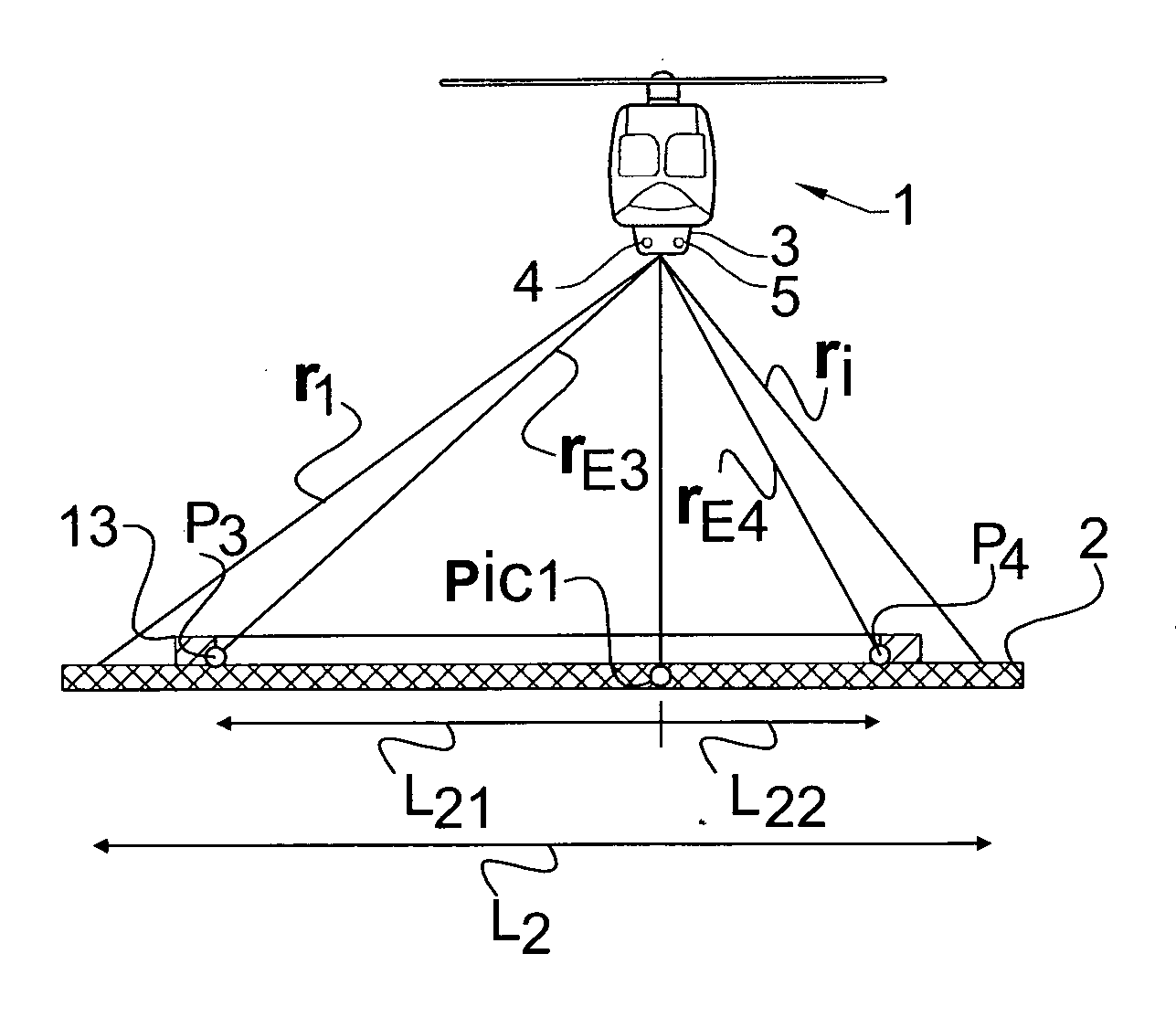
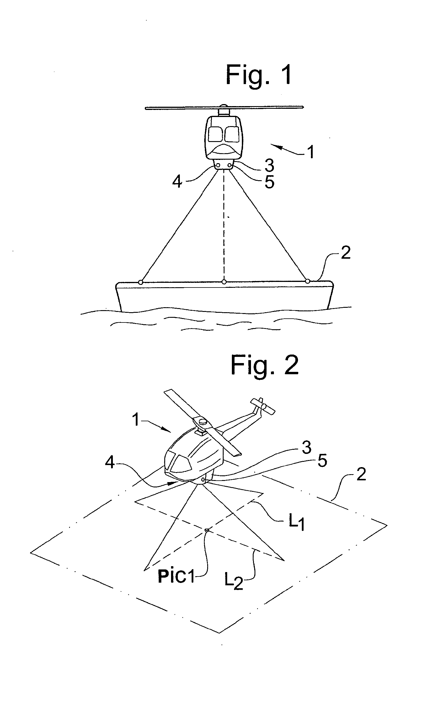
[0041]FIG. 1 shows an aerial vehicle 1 capable of VTOL, in the present case a helicopter, which has moved into a position above a surface 2 of a landing platform. The landing platform is in one example formed on a ship. The aerial vehicle 1 is equipped with a system 3 for determining the position of the aerial vehicle 1 relative to the centre of a predetermined landing area 14. The system 3 comprises adjustable beam emitters 4, 5. Wherein the beams emitters 4, 5 are arranged adjustably mounted to the body axis coordinate system of the aerial vehicle 1. Thus as the beams from the emitters is adjusted, the beam from each beam emitter is directed to trace out a line on the surface 2, with a predetermined angular relation to said body axis coordinate system of the aerial vehicle 1. In the shown example the system comprises two beam emitters 4, 5 such as at least two adjustable emitters of at least two laser distance meter assemblies. In one example each of the laser distance meter assem...


PUM


Abstract

A system arranged in an aerial vehicle for determining the position of the aerial vehicle relative to a center of a remote predetermined landing area arranged on a surface. A beam emitter is configured to emit beams towards the surface. A detector is configured to detect the beams reflected from the surface. A control is configured to control the beam emitter to emit beams onto the surface to form a plurality of lines thereon. A processor is configured to detect at least one edge providing a difference in height relative to the surface based on the detected reflected line forming beams. The edge substantially surrounds the predetermined landing area. The processor is further configured to determine the position of the aerial vehicle relative to the center of the remote predetermined landing area based on the detected at least one edge.

Description

TECHNICAL FIELD[0001]The present invention relates to a system and a method for centering of aerial vehicles above a predetermined area of a surface.[0002]Furthermore, the invention relates to software adapted to perform steps of the centering method when executed on a computer.BACKGROUND OF THE INVENTION[0003]When landing an aerial vehicle capable of VTOL (Vertical Take Off / Landing), such as an unmanned helicopter, it is important that the aerial vehicle has access to accurate information regarding movement, position and attitude relative to the ground or landing area. In particular, when trying to land on a platform of a ship, the landing process is more difficult since the sea continuously changes the attitude of the ship and the landing platform. Also the fact that the ship is moving in a specific bearing further complicates the landing on the platform. The inclination of the platform is determined by the pitch and the roll, and there is also a movement in the vertical direction...

Claims


Application Information

Patent Timeline
Patent Type & Authority Applications(United States)
IPC IPC(8): G05D1/10G01S17/87G01S5/16G01S17/86G01S17/875
CPCG01S17/023G05D1/0684G01S17/88G01S17/875G01S17/86
Inventor EHLIN, JOHANHOGSTROM, TOMAS
Owner UMS SKELDAR SWEDEN AB
Why Eureka
Try Eureka