Stationery tool

a technology for stationary devices and tools, applied in the field of stationary devices, can solve the problems of inability to adjust, extend the length of the rubber, and be not versatile in use, and achieve the effect of convenient replacement of used rubber

Inactive Publication Date: 2012-06-28
SDI CORPORATION
View PDF2 Cites 0 Cited by
  • Summary
  • Abstract
  • Description
  • Claims
  • Application Information

AI Technical Summary

Benefits of technology

[0008]The main objective of the invention is to provide a stationery tool having a rubber holding device to securely clamp a rubber and having capabilities of adjusting an extension length of the rubber and conveniently replacing a used rubber.
[0010]With such an arrangement, the rubber holding device in accordance with the present invention has capabilities of adjusting an extension length of the rubber relative to the body and conveniently replacing the rubber. The rubber can be pushed to extend out of the body for use and can be retracted completely after wiping. As to replacement, the rubber can be easily replaced by drawing the rubber holding device out from the body or rotating the rotating knob, and this is convenient in operation.
[0011]In addition, because the rubber holding device has a clamping segment and a guiding segment, the rubber can be securely clamped by the clamping segment to prevent the rubber from detaching from the body. The guiding segment can keep the rubber from being violently deformed during wiping and has capabilities of preventing the rubber from detaching from the body and of absorbing the deformation of the rubber.

Problems solved by technology

To alternately use different stationery tools is inconvenient; to prepare, carry and store different kinds of stationery tools takes a large space and is also inconvenient.
In addition, the extension length of the rubber 52 cannot be adjusted relative to the body 50 and the rubber 52 cannot be retracted into the body 50, and this is not versatile in use.
Furthermore, when the rubber 52 is used up or damaged, the used rubber 52 cannot easily be removed from the body 50 and replaced with a new one.

Method used


Image

  • Stationery tool
  • Stationery tool
  • Stationery tool

Examples


first embodiment

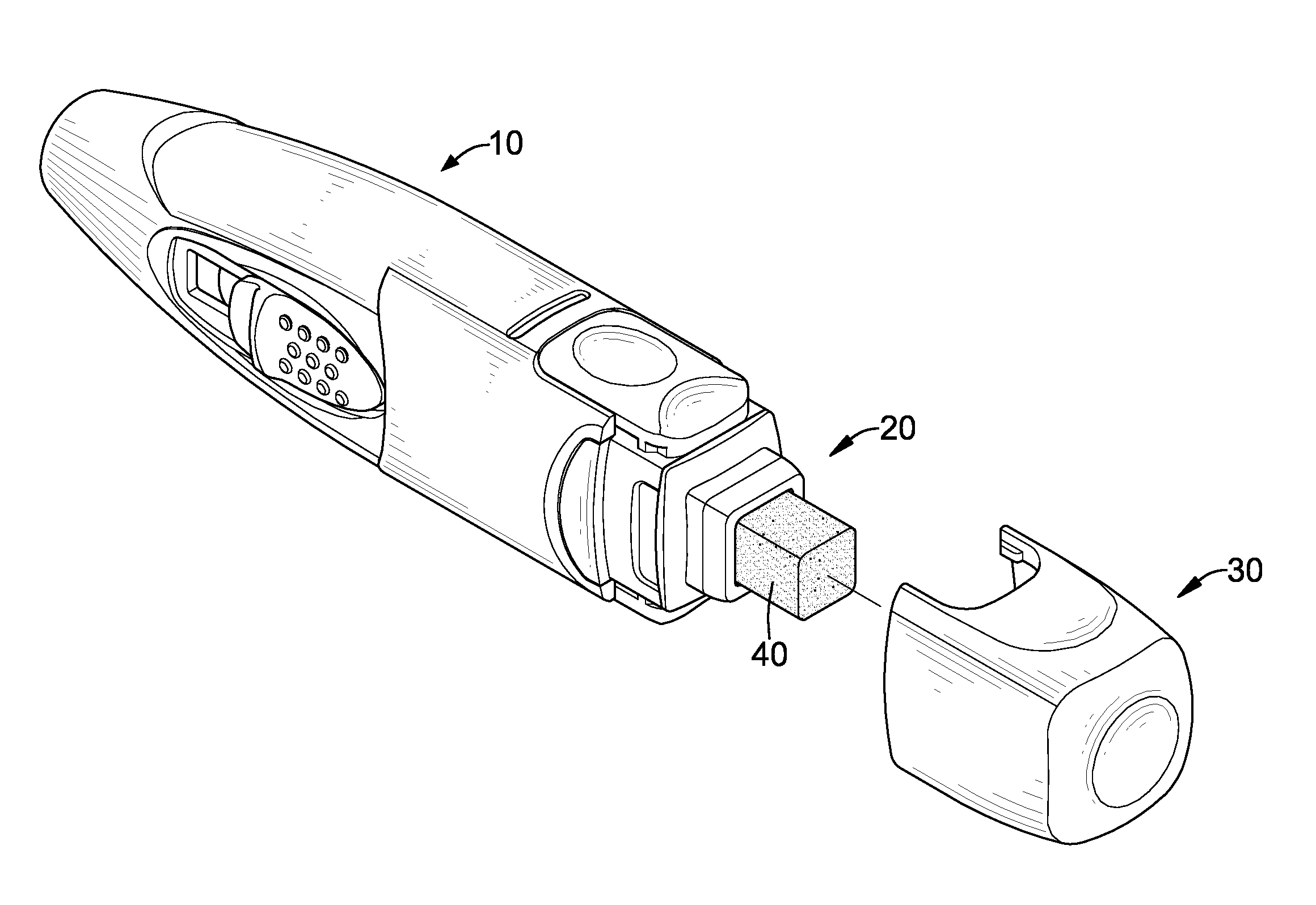
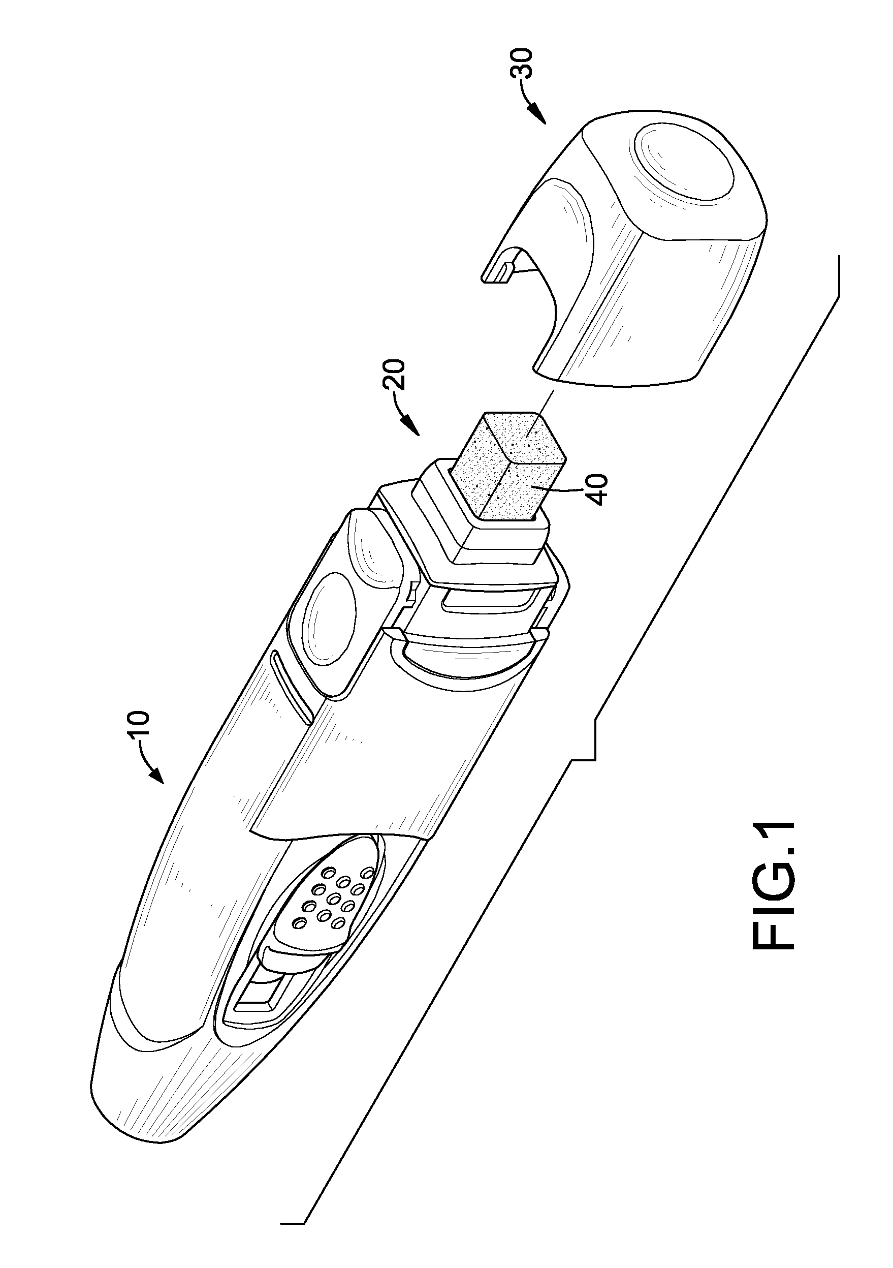
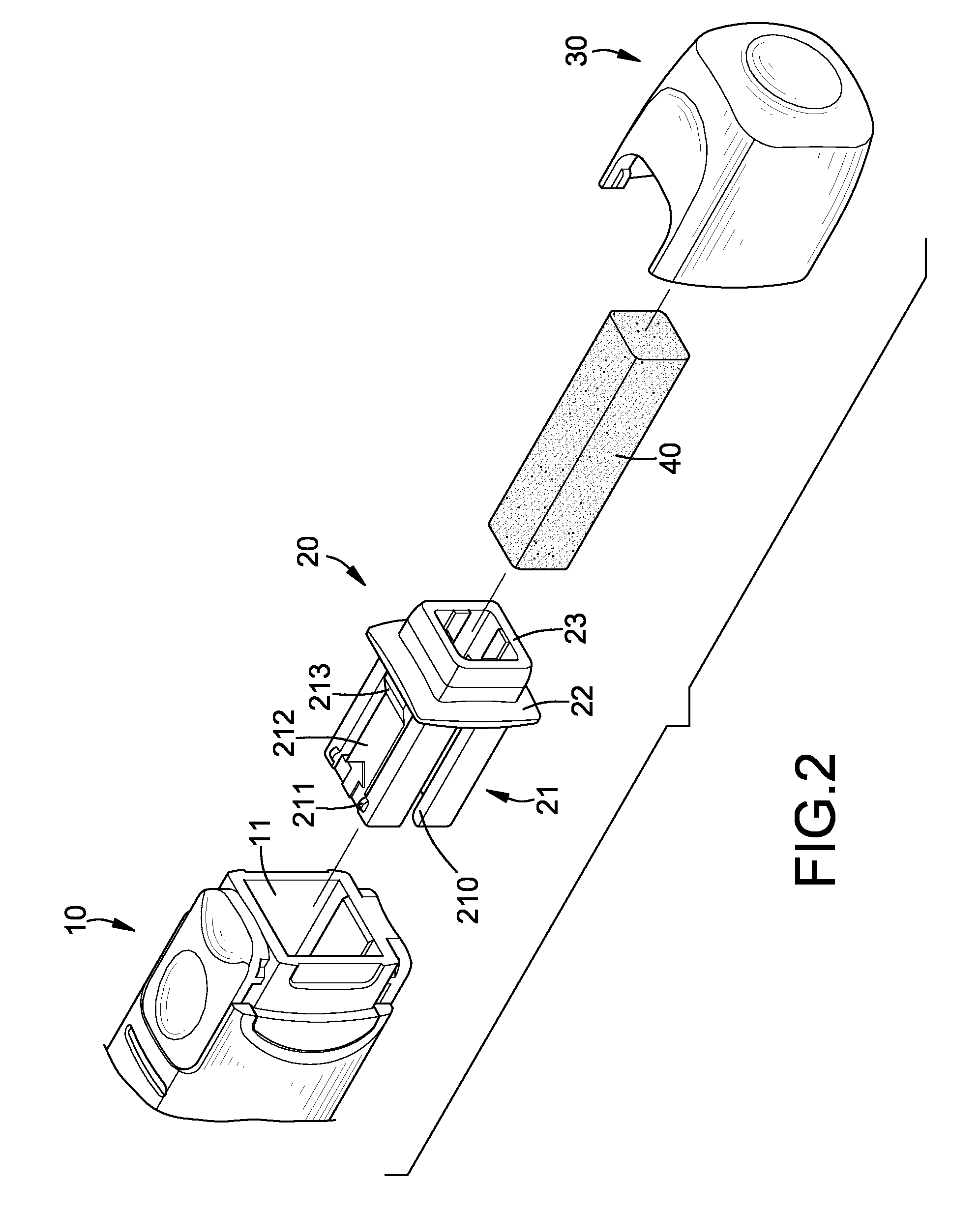
[0035]With reference to FIGS. 1 to 3, a stationery tool in accordance with the present invention comprises a body 10, a rubber holding device 20 and a cap 30.

[0036]The body 10 may be a writing tool, a correction tape dispenser, an adhesive tape dispenser or the like, is elongated and comprises a holding end, a stationery functional end and a holding recess 11. The stationery functional end is opposite to the holding end. The holding recess 11 has a mouth defined at the holding end of the body 10 and a first buckling segment 12 formed on the inner surface of the holding recess 11. The first buckling segment 12 is formed on two opposite sides of the inner surface of the holding recess 11 at an inner end opposite to the mouth. The first buckling segment 12 may be implemented as two buckling cavities formed respectively in the opposite sides of the inner surface of the holding recess 11.

[0037]The rubber holding device 20 may be a hollow rectangular frame, is mounted detachably on the bo...

third embodiment

[0052]With reference to FIGS. 8 to 11, the present invention comprises a body 10B, a detachable and rotatable rubber holding device 20B and a cap 30B.

[0053]The body 10B has a structure substantially same as that in the first embodiment and further description is omitted.

[0054]The rubber holding device 20B is detachably inserted into the holding recess 11B and comprises an outer frame 21B, a stopping flange 22B, a guiding tube 23B, a pushing slider 24B and a rotating knob 25B. The outer frame 21B is mounted detachably in the holding recess 11B and has a resilient slot 210B formed laterally in a middle portion of the outer frame 21B to divide the outer frame 21B into two half frames, such that the half frames have a resilient capability to be pressed toward each other. A second buckling segment 211B is formed on the inner ends at the outer sides of the half frames and engages the first buckling segment 12B on the body 10B to keep the rubber holding device 20B from detaching from the b...

fifth embodiment

[0066]The guiding tube 23D has an inner end integrally connected to the bottom of the holding recess 11D and an outer end extending out of the holding recess 11D. The pushing slider 24D is mounted in the guiding tube 23D, and the rotating knob 25D is rotatably mounted around the guiding tube 23D and mounted between the guiding tube 23D and the body 10D. Preferably, the rotating knob 25D has an engaging segment formed on the outer surface at the middle portion of the rotating knob 25D and rotatably engaging the positioning segment in the body 10D. The engaging segment may be an annular recess 252D corresponding to and engaging the at least one positioning flange 12D or annular positioning rib of the positioning segment, or may comprise at least one positioning flange or an annular positioning rib corresponding to and engaging the annular recess of the positioning segment. Accordingly, the rotating knob 25D is rotatably connected with the inner surface of the holding recess 11D. In th...


PUM


Abstract

A stationery tool has a body and a rubber holding device. The body has a holding end and a holding recess defined in the holding end. The rubber holding device is detachably or securely mounted in the holding recess for holding a rubber to adjust an extension length of the rubber relative to the body and has a clamping segment and a guiding segment. The clamping segment has multiple clamping protrusions for pressing against the rubber. The guiding segment extends outwardly and makes an opening of the rubber holding device have a distance from the clamping segment. Accordingly, the stationery tool has capabilities of adjusting an extension length of the rubber and conveniently replacing a used rubber.

Description

BACKGROUND OF THE INVENTION[0001]1. Field of the Invention[0002]The present invention relates to a stationery tool, and more particularly to a stationery tool having a rubber holding device for adjusting an extension length of a rubber and having an ease rubber changing capability.[0003]2. Description of Related Art[0004]Rubbers are mostly block or stick shaped individual objects enabling a user holding the rubber with one hand to wipe pencil writing marks out. To keep a rubber clean, Taiwan Utility Model Patent No. 336548, entitled “Rotation Typed Stick Object Dispenser” is provided. The dispenser of the '548 patent comprises a tubular body containing a stick typed rubber inside, and the rubber can be pushed out of or retracted into the tubular body in a rotation manner. However, the dispenser of the '548 patent is an individual object from other stationery tools, such as pencils or pens, so a user has to alternately use a pencil, a pen, a rubber or a correction tape for writing or...

Claims


Application Information

Patent Timeline
Patent Type & Authority Applications(United States)
IPC IPC(8): B43L19/00
CPCB43M99/00B43L19/0068B43L19/00
Inventor WU, CHIEN-LUNG
Owner SDI CORPORATION
Why Eureka
Try Eureka