Light-emitting unit, light-emitting device, and lighting device
- Summary
- Abstract
- Description
- Claims
- Application Information
AI Technical Summary
Benefits of technology
Problems solved by technology
Method used
Image

Examples
embodiment 1
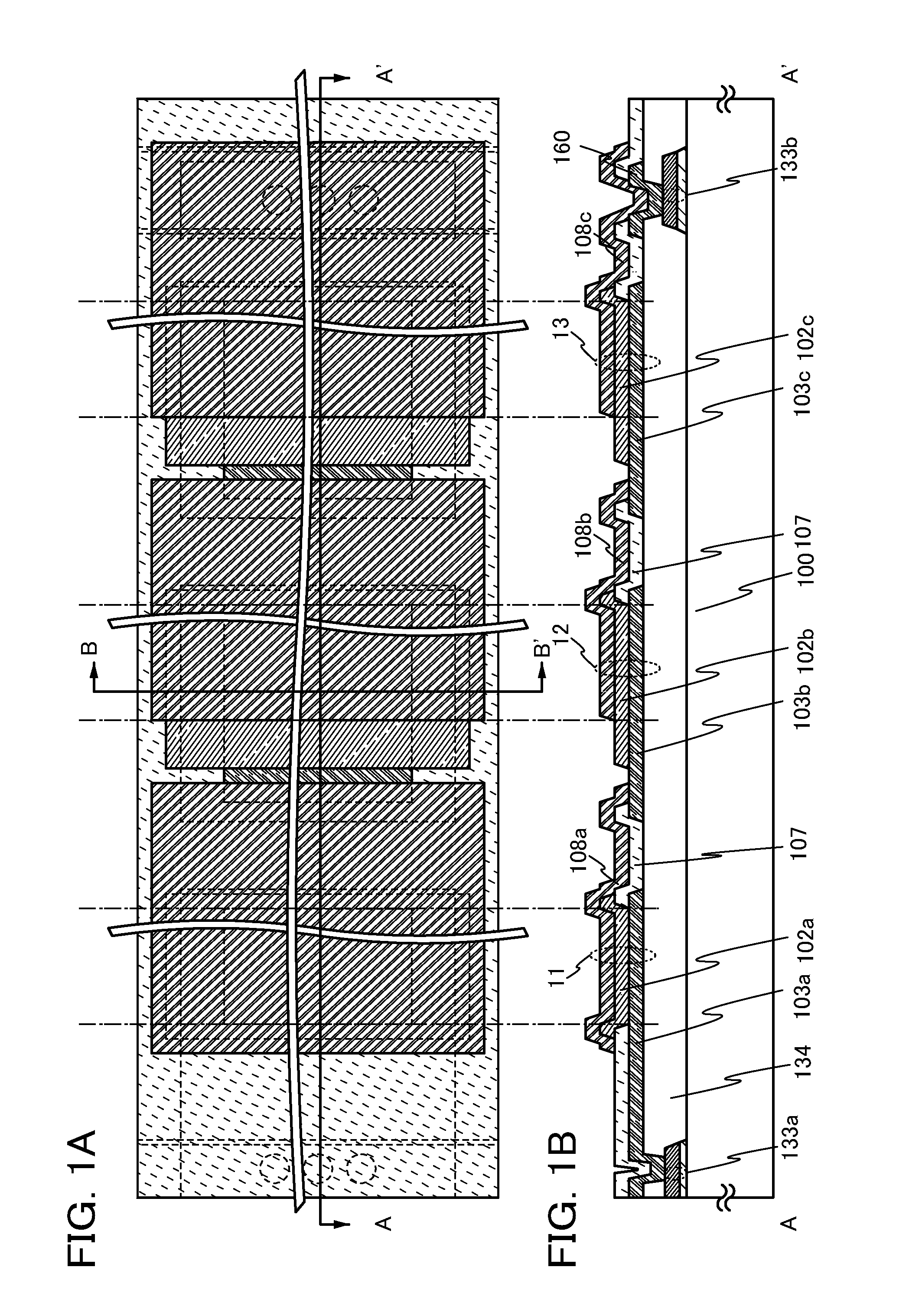
[0057]In this embodiment, light-emitting units each of which is one embodiment of the present invention will be described with reference to FIGS. 1A and 1B, FIGS. 2A and 2B, FIGS. 3A and 3B, and FIG. 14A. FIG. 1B is a cross-sectional view taken along line A-A′ in FIG. 1A. FIG. 14A is a cross-sectional view taken along line B-B′ in FIG. 1A.
Structural Example
[0058]First, structures of the light-emitting units described in this embodiment will be described.
[0059]Note that in this specification, light-emitting elements each include a lower electrode, an upper electrode, and a layer containing a light-emitting organic compound, which is interposed between the lower electrode and the upper electrode. An EL layer includes at least the layer containing a light-emitting organic compound. The EL layer can have a stacked structure in which a layer containing a substance having a high electron-transport property, a layer containing a substance having a high hole-transport property, a layer cont...
example 1
Structural Example 1
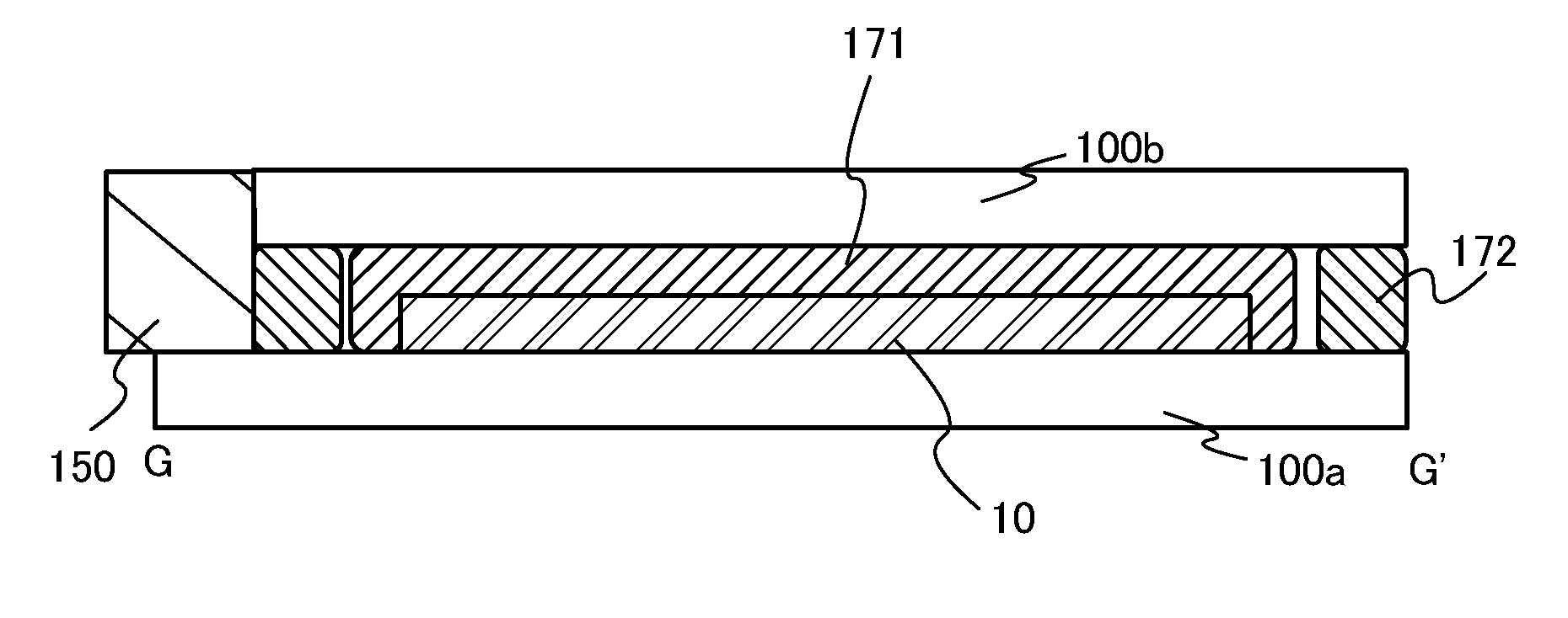
[0060]A light-emitting unit illustrated in FIGS. 1A and 1B and FIG. 14A includes a wiring 133a, a wiring 133b, a planarization layer 134, a partition wall 107, a first light-emitting element 11, a second light-emitting element 12, and a third light-emitting element 13 over a substrate 100.
[0061]The first light-emitting element 11 includes a first electrode 103a formed over the planarization layer 134, an EL layer 102a formed over the first electrode 103a, and a second electrode 108a formed over the EL layer 102a.
[0062]The second light-emitting element 12 includes a first electrode 103b formed over the planarization layer 134, an EL layer 102b formed over the first electrode 103b, and a second electrode 108b formed over the EL layer 102b.
[0063]The third light-emitting element 13 includes a first electrode 103c formed over the planarization layer 134, an EL layer 102c formed over the first electrode 103c, and a second electrode 108c formed over the EL layer 102c....
example 2
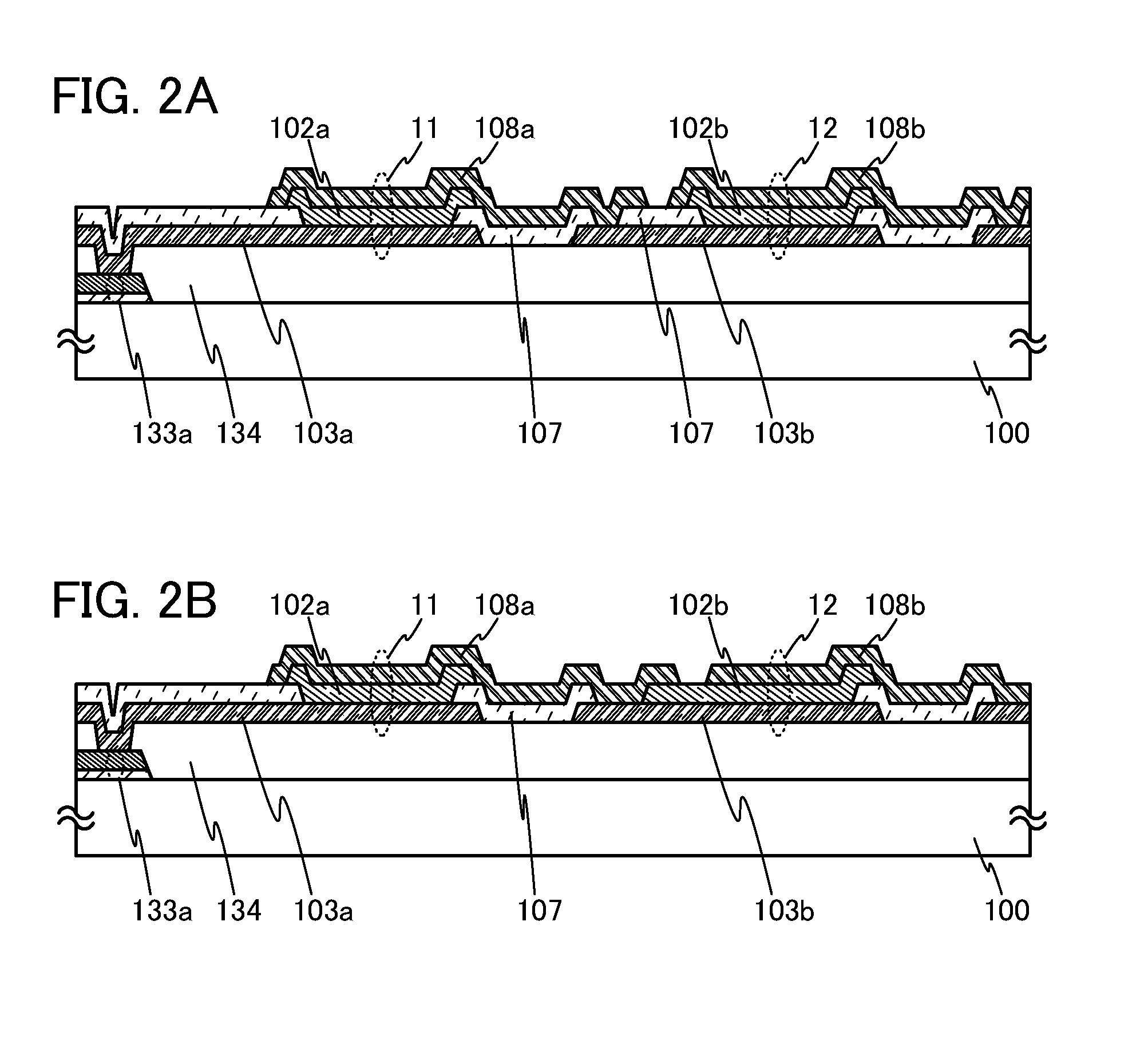
Structural Example 2
[0136]In order to obtain the structure (FIG. 2A) described in Structural Example 2, the partition wall 107 may also be formed over the first electrode in a step of forming the partition wall 107. In addition, the second electrode may be formed so that the edge portion of the second electrode overlaps with the first electrode with the partition wall 107 over the first electrode interposed therebetween.
PUM
 Abstract
Description
Claims
Application Information
 - R&D
- Intellectual Property
- Life Sciences
- Materials
- Tech Scout
- Unparalleled Data Quality
- Higher Quality Content
- 60% Fewer Hallucinations
Browse by: Latest US Patents, China's latest patents, Technical Efficacy Thesaurus, Application Domain, Technology Topic, Popular Technical Reports.
© 2025 PatSnap. All rights reserved.Legal|Privacy policy|Modern Slavery Act Transparency Statement|Sitemap|About US| Contact US: help@patsnap.com