Supercharge Your Innovation With Domain-Expert AI Agents!

Optical touch panel and method of detecting touch point positions on an optical touch panel

Active Publication Date: 2012-06-28
DYNA IMAGE CORPORATION
View PDF4 Cites 4 Cited by
  • Summary
  • Abstract
  • Description
  • Claims
  • Application Information

AI Technical Summary

Benefits of technology

[0008]Accordingly, a method of detecting touch point positions on an optical touch panel according to the present invention is provided. The optical touch panel includes a processing unit, and at least three optical detectors divided into at least two detector groups. Each of the optical detectors is configured to output a signal indicating intensities of light detected thereby. The method comprises the steps of:

Problems solved by technology

However, this patent fails to provide a solution for determining a ghost point.

Method used


Image

  • Optical touch panel and method of detecting touch point positions on an optical touch panel
  • Optical touch panel and method of detecting touch point positions on an optical touch panel
  • Optical touch panel and method of detecting touch point positions on an optical touch panel

Examples


Embodiment Construction

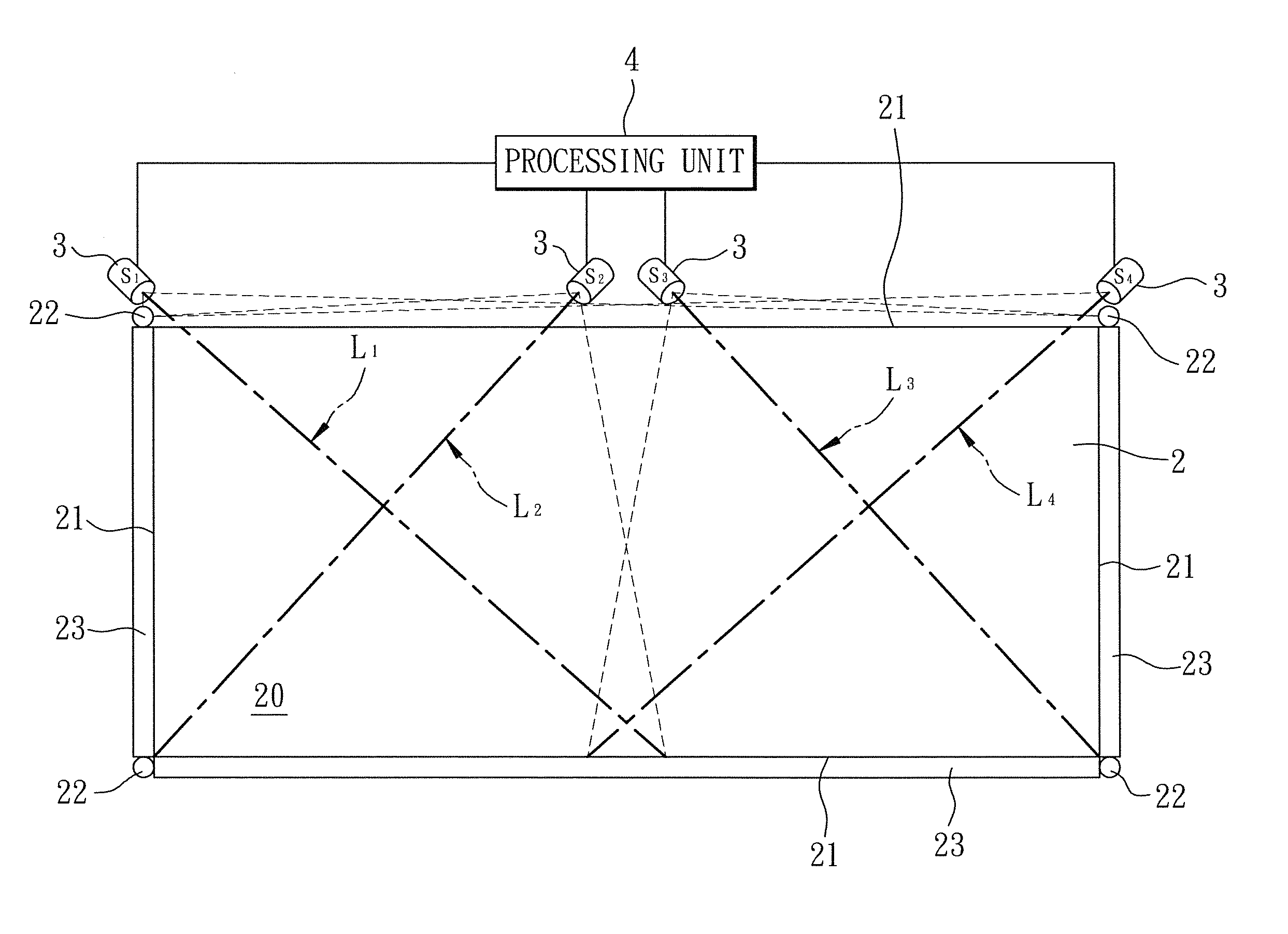
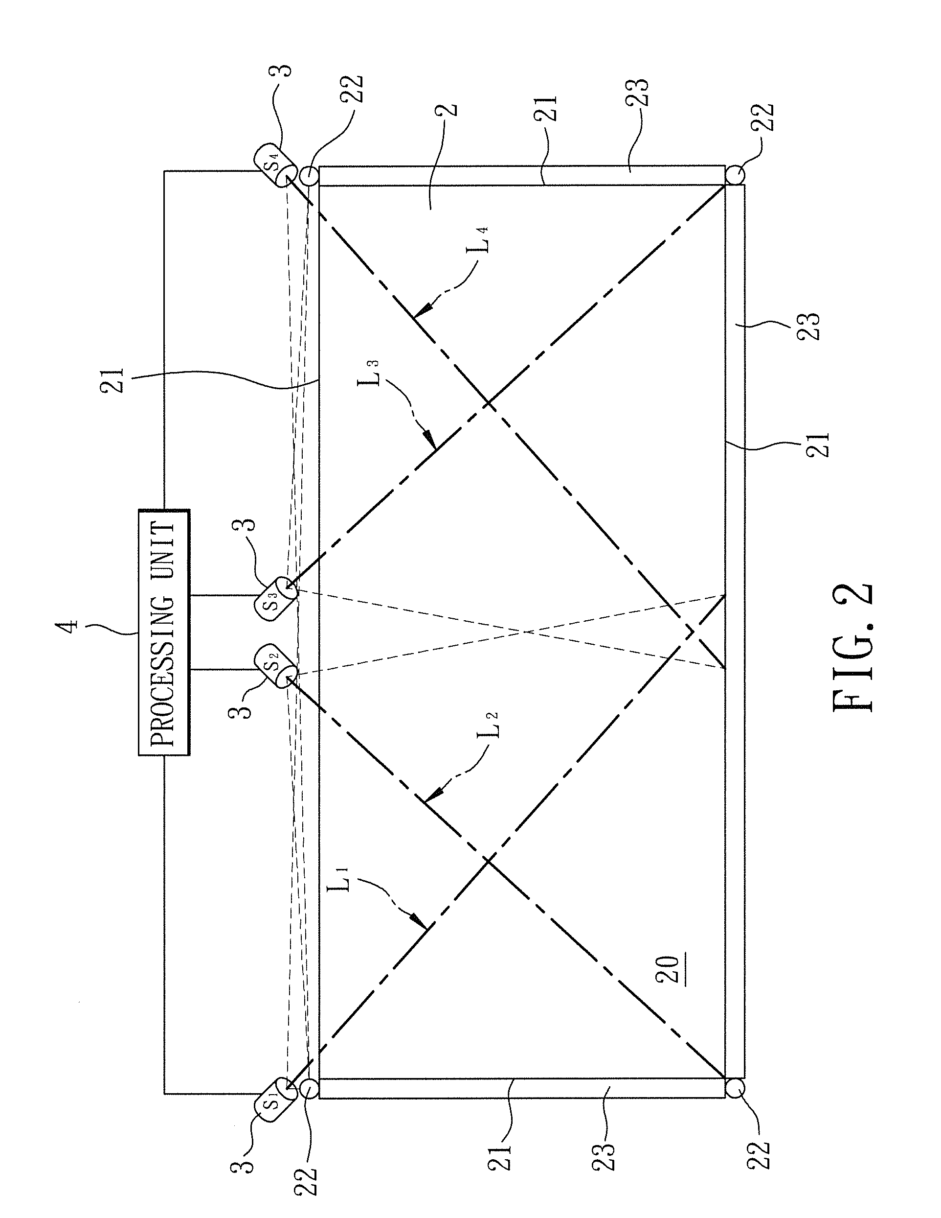
[0025]Referring to FIG. 2, a preferred embodiment of an optical touch panel according to the present invention includes a support 2 defining a surface 20 and having a periphery 21, at least one light source 22, at least one light guide 23, at least three optical detectors 3, and a processing unit 4. The surface 20 of the support 2 is configured to allow an object to make contact therewith. In this embodiment, the optical touch panel includes three of the light guides 23 surrounding at least a part of the periphery 21 of the support 2, and four of the light sources 22 arranged for directing light (such as infrared light, which is non-visible light) along the light guides 23 so that the light guides 23 are operative to direct the light received from the light sources 22 across the surface 20. The optical detectors 3 are spaced apart from each other, and are arranged along at least one side of the periphery 21 of the support 2. Each of the optical detectors 3 is operable to output a si...


PUM


Abstract

An optical touch panel and a method of detecting touch point positions on an optical touch panel are provided. The optical touch panel includes a processing unit, and at least three optical detectors divided into at least two detector groups. Each of the optical detectors is configured to output a signal indicating intensities of light detected thereby, and is associated with a detection range. The processing unit is configured to receive the signals from the optical detectors, to determine which of the optical detectors detect touch points within the respective detection range according to the signals received by the processing unit, and to obtain an optimum set of coordinates for at least one of the touch points with respect to an optimum detector group which is one of the detector groups formed by the optical detectors that detect the touch points.

Description

CROSS-REFERENCE TO RELATED APPLICATION[0001]This application claims priority of Chinese Application No. 201010613520.1, filed on Dec. 24, 2010.BACKGROUND OF THE INVENTION[0002]1. Field of the Invention[0003]The present invention relates to an optical touch panel and a method of detecting touch point positions on an optical touch panel, more particularly to an optical touch panel and a method of detecting multiple touch point positions on an optical touch panel.[0004]2. Description of the Related Art[0005]Referring to FIG. 1, a conventional optical touch panel 1 includes a support 11 defining a surface 111, light sources 12, a pair of optical detectors 13, and a processing unit 14. Each of the optical detectors 13 is configured to output a signal indicating intensities of light detected thereby. The processing unit 14 is operable, according to the signals from the optical detectors 13, to compute coordinates of at least one touch point 10 on the surface 111 of the support 11 using tr...

Claims


Application Information

Patent Timeline
IPC IPC(8): G06F3/042
CPCG06F3/042G06F3/0416G06F3/04186
Inventor CHEN, JAU-YUCHEN, CHIH-HAO
Owner DYNA IMAGE CORPORATION
Features
  • R&D
  • Intellectual Property
  • Life Sciences
  • Materials
  • Tech Scout
  • Unparalleled Data Quality
  • Higher Quality Content
  • 60% Fewer Hallucinations
Learn More