Single detector receiver for multi-beam LADAR systems

a single detector and receiver technology, applied in the field of ladar systems, can solve the problems of statistically low performance, non-linear and inconsistent apds between devices, and difficult channel equalization,

Active Publication Date: 2006-09-07
LOCKHEED MARTIN CORP
View PDF2 Cites 125 Cited by
  • Summary
  • Abstract
  • Description
  • Claims
  • Application Information

AI Technical Summary

Problems solved by technology

Although highly sensitive in the avalanche mode of operation, APDs can be unpredictable with non-linear and inconsistent responsivity between devices.
These problems are exacerbated when APDs are used in multi-channel systems because their gain variation can m...

Method used


Image

  • Single detector receiver for multi-beam LADAR systems
  • Single detector receiver for multi-beam LADAR systems
  • Single detector receiver for multi-beam LADAR systems

Examples


Embodiment Construction

[0018] Illustrative embodiments of the invention are described below. In the interest of clarity, not all features of an actual implementation are described in this specification. It will of course be appreciated that in the development of any such actual embodiment, numerous implementation-specific decisions must be made to achieve the developers' specific goals, such as compliance with system-related and business-related constraints, which will vary from one implementation to another. Moreover, it will be appreciated that such a development effort, even if complex and time-consuming, would be a routine undertaking for those of ordinary skill in the art having the benefit of this disclosure.

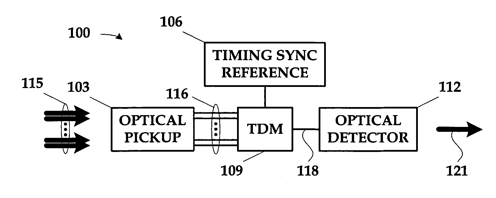
[0019]FIG. 1 illustrates an optical detection apparatus 100 for use in a multi-beam LADAR system. The optical detection apparatus 100 comprises an optical pickup 103, a timing synchronization reference 106, a time domain multiplexer (“TDM”) 109, and an optical detector 112. The optical pickup 1...


PUM


Abstract

A LADAR apparatus and a method for use in receiving a LADAR signal are disclosed. The apparatus includes an optical pickup capable of picking up a plurality of optical signals; a timing synchronization reference; a time domain multiplexer capable of multiplexing the optical signals into a multiplexed optical signal relative to the timing synchronization reference; and an optical detector capable of detecting the multiplexed optical signal. The method include time domain multiplexing a plurality of LADAR signals into multiplexed LADAR signal; detecting the multiplexed LADAR signal; and demultiplexing the detected LADAR signal.

Description

BACKGROUND OF THE INVENTION [0001] 1. Field of the Invention [0002] The present invention pertains to LADAR systems, and, more particularly, to a LADAR receiver for use in a multi-beam LADAR system. [0003] 2. Description of the Related Art [0004] Many military and civilian applications rely on optical techniques such as laser detection and ranging (“LADAR”). At a very high level, LADAR works much like the more familiar radio wave detection and ranging (“RADAR”), in which radio waves are transmitted into the environment and reflected back, the reflections giving range and position information for the objects that generate them. LADAR does roughly the same thing, but using light rather than radio waves. Although there are some significant differences in performance, they are similar in at least this one basic respect. [0005] Some LADAR systems employ a laser signal that is a pulsed, split-beam laser signal. That is, the LADAR transmitter transmits a laser signal in short bursts rather...

Claims


Application Information

Patent Timeline
IPC IPC(8): G01C3/08H04J14/00H04J14/08G01S7/486
CPCG01S7/4818G01S7/486G01S7/499G01S17/42
Inventor LIEBMAN, LIONEL D.FLOCKENCIER, STUART W.FLOWERS, EDWARD M.LARSON, DON A.
Owner LOCKHEED MARTIN CORP
Why Eureka
Try Eureka