
Apparatus and method for stereo matching

a technology of stereo matching and apparatus, applied in the field of stereo image matching apparatus and method, can solve the problems of difficult to completely solve the phenomenon, image matching error may be caused, horizontal stripe appears in the image, etc., and achieves the effect of reducing the noise of steak, improving sharpness, and accurate image matching results

Inactive Publication Date: 2012-06-28
ELECTRONICS & TELECOMM RES INST
View PDF4 Cites 29 Cited by
  • Summary
  • Abstract
  • Description
  • Claims
  • Application Information

AI Technical Summary

Benefits of technology

The present invention provides an apparatus and method for matching images that can reduce steak noise, improve sharpness, and obtain accurate image matching results even when image brightness between left and right cameras is different. This is achieved by performing a dynamic programming using energy values of nodes corresponding to a pair of pixels of a left image and a right image, obtained through a census transform and support weights. The technical effects of the invention include reducing the steak noise, improving sharpness, and achieving accurate image matching results.

Problems solved by technology

However, when an epipolar line is distorted due to the inaccuracy of the calibration of the left and right cameras, a steak noise in which a horizontal stripe appears in the image may be caused.
Actually, it is difficult to accurately match the calibration of the left and right cameras and since there is a unique error between the left and right cameras, it is difficult to completely solve the phenomenon.
In addition, since the stereo matching technology according to the related art is designed under the premise that only brightness information in the image information of the left and right cameras is used and the image brightness of the left and right cameras matches each other, the image matching error may be caused when brighter light is incident on the specific camera between the left and right cameras.

Method used


Image

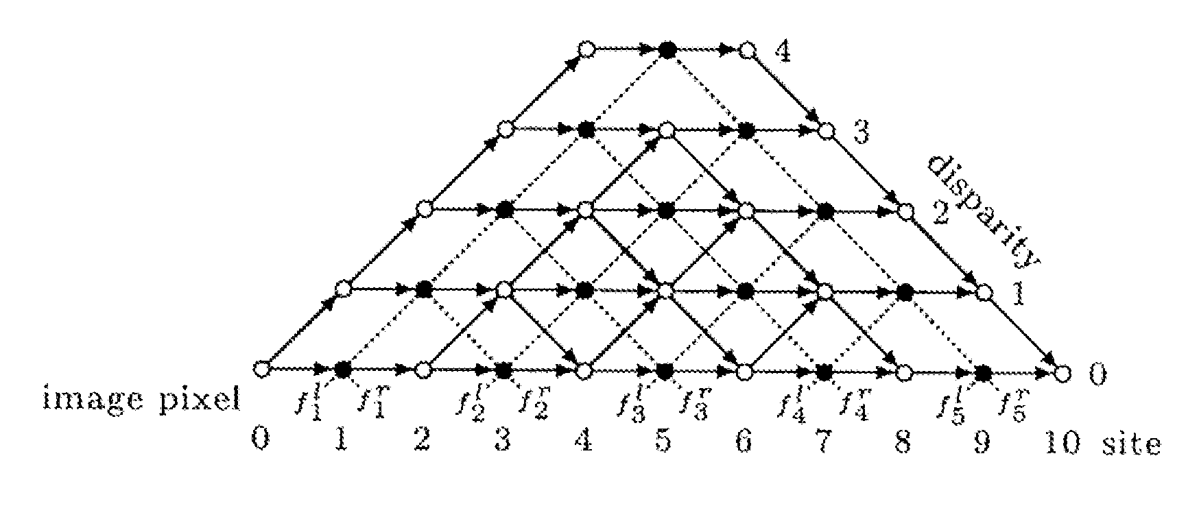
  • Apparatus and method for stereo matching
  • Apparatus and method for stereo matching
  • Apparatus and method for stereo matching

Examples


Embodiment Construction

[0023]Hereinafter, exemplary embodiments of the present invention will be described in detail with reference to the accompanying drawings. First of all, we should note that in giving reference numerals to elements of each drawing, like reference numerals refer to like elements even though like elements are shown in different drawings. In describing the present invention, well-known functions or constructions will not be described in detail since they may unnecessarily obscure the understanding of the present invention. It should be understood that although exemplary embodiment of the present invention are described hereafter, the spirit of the present invention is not limited thereto and may be changed and modified in various ways by those skilled in the art.

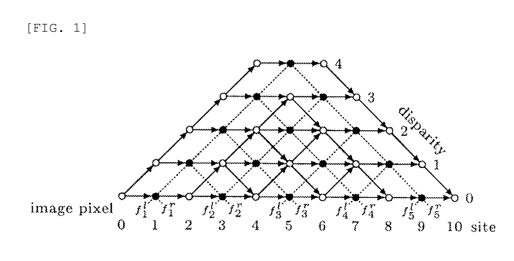
[0024]First, a dynamic programming type used in an exemplary embodiment of the present invention will be described prior to describing the exemplary embodiments of the present invention.

[0025]The dynamic programming type forms a...


PUM


Abstract

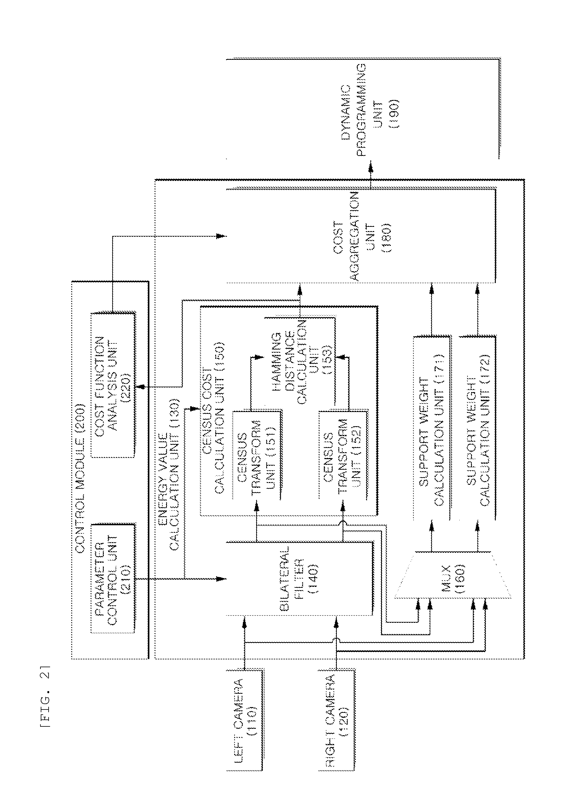
An image matching apparatus includes a bilateral filter that filters a left image and a right image to output a second left image and a second right image; a census cost calculation unit performing census transform on a window based on a first pixel of the second left image and a window based on a second pixel of the second right image to calculate a census cost corresponding to a pair of pixels of the first and second pixels; a support weight calculation unit obtaining support weights of the left and right images or the second left and second right images; a cost aggregation unit obtaining energy values of nodes corresponding to the pair of pixels of the first and second pixels using the census cost and the support weights; and a dynamic programming unit performing image matching using dynamic programming by the energy values of each node obtained.

Description

CROSS-REFERENCE TO RELATED APPLICATIONS[0001]This application claims priority to and the benefit of Korean Patent Application NO. 10-2010-0134082 filed in the Korean Intellectual Property Office on Dec. 23, 2010, the entire contents of which are incorporated herein by reference.TECHNICAL FIELD[0002]The present invention relates to a stereo image matching apparatus and method, and more particularly, to a stereo image matching apparatus and method using a dynamic programming mechanism.BACKGROUND ART[0003]Stereo image matching technology for obtaining a three-dimensional stereoscopic image is a technology of extracting stereoscopic image information from two images input through cameras mounted left and right. The stereo image matching technology obtains a stereo image by capturing the same subject by using two cameras that are disposed at different positions on the same line. The stereo image matching technology may be considered as a process of calculating a distance up to the subjec...

Claims


Application Information

Patent Timeline
Patent Type & Authority Applications(United States)
IPC IPC(8): G06K9/68
CPCG06T7/0075G06T2207/20028G06T7/0022G06T7/593G06T7/97H04N5/21H04N13/261
Inventor CHANG, JI HOLIM, EUL GYOONSHIN, HO CHULCHO, JAE II
Owner ELECTRONICS & TELECOMM RES INST
Learn More