
Method of Manufacturing a Light Emitting, Power Generating or Other Electronic Apparatus

a technology of power generation or electronic equipment, applied in the field of light emitting and photovoltaic technology, can solve the problems of labor intensive and expensive, led-based lighting devices which are generally too expensive for many consumer applications, time-consuming, labor-intensive and expensive,

Active Publication Date: 2012-06-28
NTHDEGREE TECH WORLDWIDE
View PDF17 Cites 50 Cited by
  • Summary
  • Abstract
  • Description
  • Claims
  • Application Information

AI Technical Summary

Benefits of technology

[0056]In an exemplary embodiment, a method of fabricating an electronic device comprises: depositing one or more first conductors; and depositing a plurality of diodes suspended in a mixture of a first solvent and a viscosity modifier.
[0057]In another exemplary embodiment, a method comprises: depositing a plurality of diodes suspended in a mixture of first solvent and a viscosity modifier on a first side of an optically transmissive base, each diode of the plurality of diodes having a plurality of first terminals on a first side and one second terminal on the first side, each diode of the plurality of diodes having a lateral dimension between about 10 to 50 microns and a height between 5 to 25 microns; depositing one or more first conductors coupled to the first terminals; depositing at least one dielectric layer coupled to the one or more first conductors; depositing one or more second conductors coupled to the second terminals; and depositing a first phosphor layer on a second side of the optically transmissive base.
[0058]In another exemplary embodiment, a method comprises: depositing one or more first conductors on a first side of a base; depositing a plurality of diodes suspended in a mixture of a first solvent and a viscosity modifier over the one or more first conductors, each diode of the plurality of diodes having a first terminal on a first side and a second terminal on a second side, each diode of the plurality of diodes having a lateral dimension between about 10 to 50 microns and a height between 5 to 25 microns; depositing at least one dielectric layer over the plurality of diodes and the one or more first conductors; depositing one or more optically transmissive second conductors over the dielectric layer; and depositing a first phosphor layer.
[0059]In another exemplary embodiment, a composition comprises: a plurality of two-terminal integrated circuits, each two-terminal integrated circuit of the plurality of two-terminal integrated circuits less than about 75 microns in any dimension; a first solvent; a second solvent different from the first solvent; and a viscosity modifier; wherein the composition has a viscosity substantially about 50 cps to about 25,000 cps at about 25° C. In various exemplary embodiments, the plurality of two-terminal integrated circuits comprise a two-terminal integrated circuit selected from the group consisting of: diodes, light emitting diodes, photovoltaic diodes, resistors, inductors, capacitors, RFID integrated circuits, sensor integrated circuits, and piezo-electric integrated circuits.
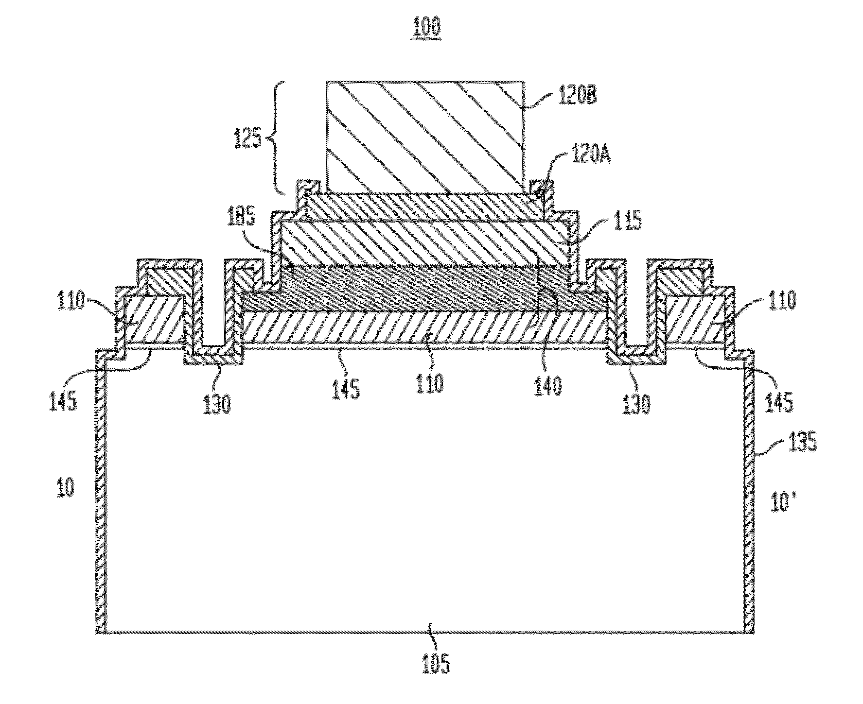
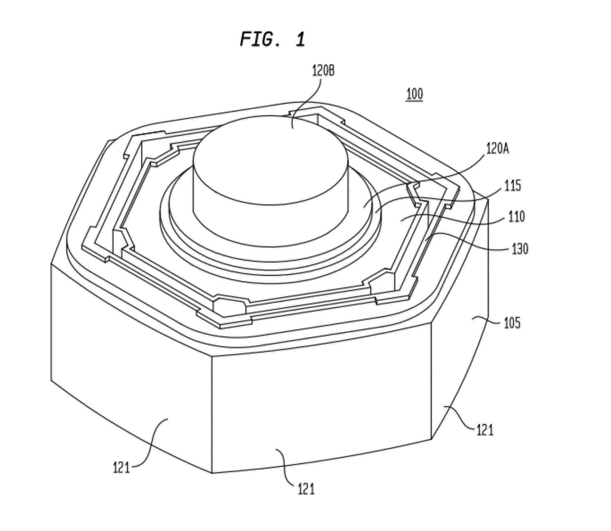
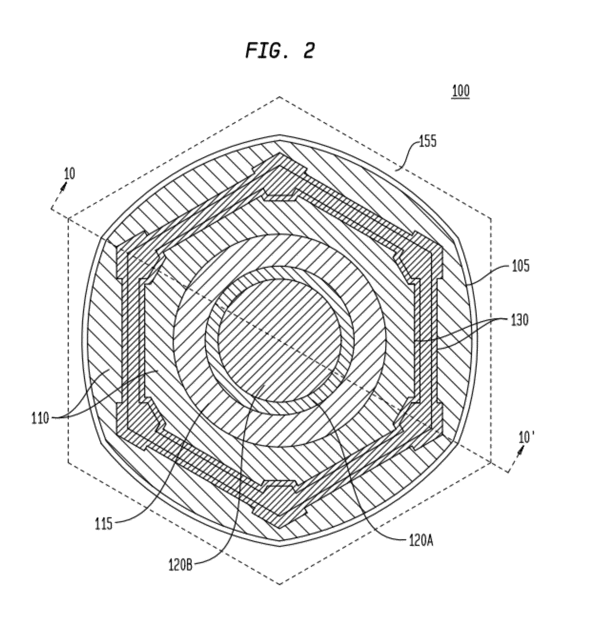
[0060]In another exemplary embodiment, an apparatus comprises: a base; a plurality of two-terminal integrated circuits, each two-terminal integrated circuit of the plurality of two-terminal integrated circuits less than about 75 microns in any dimension; at least a trace amount of a first solvent; a film substantially surrounding each diode of the plurality of diodes, the film comprising a methylcellulose resin and having a thickness between about 10 nm to 300 nm; one or more first conductors coupled to the plurality of two-terminal integrated circuits; a first dielectric layer coupled to the one or more first conductors; and one or more second conductors coupled to the plurality of two-terminal integrated circuits.
[0061]In another exemplary embodiment, a composition comprises: a plurality of two-terminal integrated circuits, each two-terminal integrated circuit of the plurality of two-terminal integrated circuits less than about 75 microns in any dimension; a first solvent; a second solvent different from the first solvent; a plurality of substantially chemically inert particles having a range of sizes between about 10 to about 100 microns and present in an amount of about 0.1% to 2.5% by weight; and a viscosity modifier; wherein the composition has a viscosity substantially about 50 cps to about 25,000 cps at about 25° C.

Problems solved by technology

This process is time consuming, labor intensive and expensive, resulting in LED-based lighting devices which are generally too expensive for many consumer applications.
This process is also time consuming, labor intensive and expensive, resulting in photovoltaic devices which are also too expensive for widespread use without being subsidized by third parties or without other governmental incentives.
The trapezoidal-shaped diodes instead settle out rapidly into clumps of diodes adhering to each other, are unable to be maintained in a suspension or otherwise dispersed within the solvent, and require active sonication or stirring immediately before use.
Such trapezoidal-shaped diodes in a solvent cannot be utilized as a diode-based ink capable of being stored, packaged or otherwise used as an ink, and further are unsuitable for use in a printing process.
These recent developments for diode-based technologies remain too complex and expensive for LED-based devices and photovoltaic devices to achieve commercial viability.

Method used


Image

  • Method of Manufacturing a Light Emitting, Power Generating or Other Electronic Apparatus
  • Method of Manufacturing a Light Emitting, Power Generating or Other Electronic Apparatus
  • Method of Manufacturing a Light Emitting, Power Generating or Other Electronic Apparatus

Examples


Embodiment Construction

[0175]While the present invention is susceptible of embodiment in many different forms, there are shown in the drawings and will be described herein in detail specific exemplary embodiments thereof, with the understanding that the present disclosure is to be considered as an exemplification of the principles of the invention and is not intended to limit the invention to the specific embodiments illustrated. In this respect, before explaining at least one embodiment consistent with the present invention in detail, it is to be understood that the invention is not limited in its application to the details of construction and to the arrangements of components set forth above and below, illustrated in the drawings, or as described in the examples. Methods and apparatuses consistent with the present invention are capable of other embodiments and of being practiced and carried out in various ways. Also, it is to be understood that the phraseology and terminology employed herein, as well as...


PUM


Abstract

An exemplary printable composition of a liquid or gel suspension of diodes comprises a plurality of diodes, a first solvent and / or a viscosity modifier. An exemplary method of fabricating an electronic device comprises: depositing one or more first conductors; and depositing a plurality of diodes suspended in a mixture of a first solvent and a viscosity modifier. Various exemplary diodes have a lateral dimension between about 10 to 50 microns and about 5 to 25 microns in height. Other embodiments may also include a plurality of substantially chemically inert particles having a range of sizes between about 10 to about 50 microns.

Description

CROSS-REFERENCE TO RELATED APPLICATIONS[0001]This application is a conversion of and claims priority to U.S. Provisional Patent Application Ser. No. 61 / 379,225, filed Sep. 1, 2010, inventors William Johnstone Ray et al., entitled “Printable Composition of a Liquid or Gel Suspension of Diodes”, which is commonly assigned herewith, the entire contents of which are incorporated herein by reference with the same full force and effect as if set forth in their entirety herein, and with priority claimed for all commonly disclosed subject matter.[0002]This application is a conversion of and claims priority to U.S. Provisional Patent Application Ser. No. 61 / 379,284, filed Sep. 1, 2010, inventors William Johnstone Ray et al., entitled “Light Emitting, Photovoltaic and Other Electronic Apparatus”, which is commonly assigned herewith, the entire contents of which are incorporated herein by reference with the same full force and effect as if set forth in their entirety herein, and with priority ...

Claims


Application Information

Patent Timeline
Patent Type & Authority Applications(United States)
IPC IPC(8): H01L21/56
CPCH01L21/6836H01L33/005H01L27/3281H01L33/20H01L33/38H01L33/382H01L51/52H01L51/5203H01L51/56H01L2924/09701H01L24/24H01L2224/24137H01L2224/32225H01L2224/73267H01L2224/95101H01L2924/13091H01L25/048H01L31/1876H01L24/95H01L2924/13062H01L2924/12041H01L2924/1305H01L51/42H01L27/142H01L27/15H01L2924/1306H01L27/301H01L27/32H01L2924/13034H01L2924/13033H01L2924/00H01L2924/00014H01L31/03044H01L31/035281H01L31/068H01L31/0475H01L2924/12042Y02E10/544Y02E10/547H01L2924/14Y02P70/50H10K59/90H10K59/17H10K71/00H10K59/805H10K50/80H10K50/805
Inventor LOWENTHAL, MARK DAVIDRAY, WILLIAM JOHNSTONESHOTTON, NEIL O.BLANCHARD, RICHARD A.LEWANDOWSKI, MARK ALLANORAW, BRADBALDRIDGE, JEFFREYPEROZZIELLO, ERIC ANTHONY
Owner NTHDEGREE TECH WORLDWIDE
Learn More