Femtocell arrangements

a cell arrangement and cell technology, applied in the field of cell arrangement, can solve the problems of difficult for the target network to use measurements, the gateway cannot rely on the reported value of the target cell psc to uniquely identify, and the 3gpp standard message does not provide a mechanism for the source cell, etc., to achieve the effect of facilitating handover and extending the coverage area

Inactive Publication Date: 2012-06-28
ALCATEL LUCENT SAS
View PDF4 Cites 8 Cited by
  • Summary
  • Abstract
  • Description
  • Claims
  • Application Information

AI Technical Summary

Benefits of technology

[0010]According to the invention, a femtocell arrangement comprises a plurality of femtocells deployed over a region. A border femtocell at an entrance to the region is configured to operate at a higher transmit power level than neighboring femtocells to provide a larger area coverage than that provided by neighboring femtocells. By operating border femtocells at a higher transmit power than other femtocells in a building, for example, this tends to “attract” UEs as they roam towards the building. This assists with the UEs attaching, and hence attempting to handover, to the border femto cells, rather than to any of the other femtocells that may be installed in the building. As the Femto Gateway is aware that any attachment is likely to be to a border Femto, it facilitates handover by aiding the identification of the target femtocell. The region over which the plurality of femtocells is deployed may be, for example, an office, a building, an outdoor area, or partially outdoors and partially indoors.
[0011]In one embodiment, the border femtocell has an assigned primary scrambling code (PSC) that identifies it as a border femtocell. The special PSC assists the Femto Gateway to make a swift identification as to which femtocell a UE is handing over to, as the number of entrances and hence number of “border” femto cells is likely to be a small number in comparison to the number of other femtocells deployed in such an environment. This has the advantage of minimising the delay in the Femto network when handling an incoming handover request, hence reducing the risk of impacting the quality of service to the end user. The special PSC may be assigned to a border Femto by the femto management system, based on knowledge of where it is deployed, for example, at the entrance to a building. This contrasts with the approach described previously in which PSCs are autoconfigured and not specially assigned to a specific Femto or specific Femtos.

Problems solved by technology

Therefore, it is difficult for the target network to use measurements supplied by the UE to automatically determine the actual target cell when performing either macro to Femto, or Femto to Femto Handover procedures.
However existing 3GPP standard messages do not provide a mechanism for the source cell to uniquely identify the target cell, as the UE will not report the Cell ID of the target cell in measurement reports to the source cell.
However, when PSCs are re-used, the Gateway cannot rely on the reported value of the target cell PSC to uniquely identify it.
Where the Gateway, or the source Femto, is not able to uniquely determine the target femtocell from the information provided by the UE in the source cell, it makes it difficult for the Gateway or source Femto to decide to which femtocell the Handover Request should be forwarded.
This solution is likely to lead to an increase in the duration of the handover procedure, which may in turn impact the end user's on-going call, for example, leading to packet loss or even call drop.
However it will be appreciated that such an approach is extremely wasteful of resources and may soon become unmanageable as the number of deployed femto base stations and user equipment increases.
Hence any degradation to that service is potentially significant as it can negatively impact the enterprise user's perception of the value they are receiving from paying for that premium service.

Method used


Image

  • Femtocell arrangements
  • Femtocell arrangements
  • Femtocell arrangements

Examples


Embodiment Construction

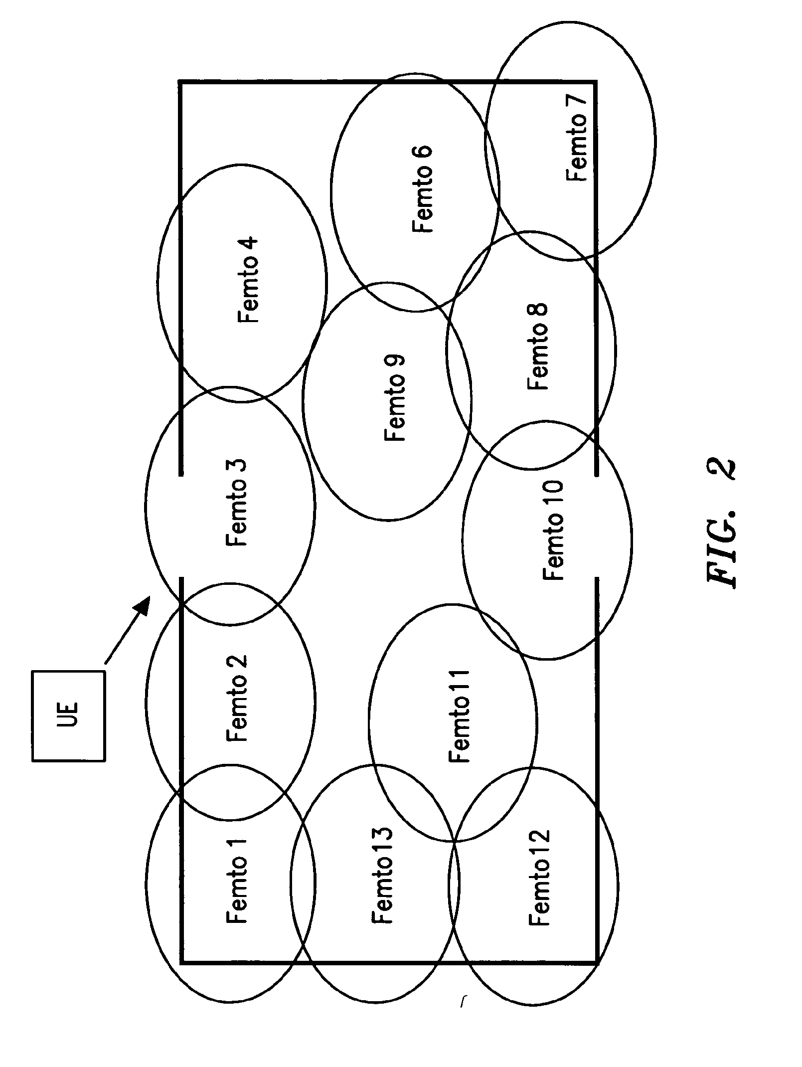
[0019]With reference to FIG. 2, which is an illustrative arrangement not in accordance with the invention and provided for the purposes of understanding, an office building has a plurality of femtocells, Femto 1 to Femto 13, deployed within it. Those Femtos located at the edge of the office radiate outside it. Hence, when a UE approaches the entrance to the office, as shown, it may attempt to attach to any femtocell that meets its handover criteria. For example, the UE 2 may equally attempt to attach to Femto 1, 2, or 3 as it approaches the entrance to the office. Depending on the number of PSCs re-used within the deployment, the Femto Gateway may not be able to make a unique identification of the handover target cell from the information it receives from the UE. Thus, handover may be delayed and adversely affect the operation of the UE.

[0020]With reference to FIG. 3, in an arrangement in accordance with the invention, a plurality of Femtos 1 to 13 is deployed in an office or other ...


PUM


Abstract

A femtocell arrangement comprises a plurality of femtocells Femto 1 to Femto 13 having coverage distributed over a region, such as, for example, an office. A border femtocell, Femto 3 or Femto 10, of said plurality has coverage at an entrance to the region and is arranged to operate at a higher transmit power level to provide a larger coverage area than that provided by neighboring femtocells. In addition, the border femtocell may be allocated a specific Primary Scrambling Code (PSC) to show its designation as a border femtocell. An approaching user equipment UE 1 or UE 2 tends to attach to the higher transmit power border femtocells. The Femto Gateway managing the connection is aware of the likelihood that an approaching UE will tend to attach to a border femtocell, and this is further confirmed by the use of a specific PSC. Hence, handover is expedited as the most suitable femtocells may be chosen as targets for handover.

Description

FIELD OF THE INVENTION[0001]The present invention relates to femtocell arrangements.BACKGROUND[0002]Femtocells (also referred to as “Femtos” in this specification) are low power, low cost, generally user-deployed base stations that are able to provide exceptional cellular service in residential or enterprise environments, with a typical coverage range of tens of meters. They have extensive auto-configuration and self-optimization capabilities to enable a simple ‘plug and play’ deployment, and are designed to automatically integrate themselves in an existing macrocellular network. Femtocells typically use the customer's broadband internet connection (e.g. Digital Subscriber Line (DSL), cable, etc.) as backhaul.[0003]A typical femtocell architecture is shown in FIG. 1, where the ‘Home cell’ shown on the right hand side is a femtocell and is connected to a Home cell, or Femtocell, Controller / Gateway. In the particular architecture illustrated, elements on the left hand side of the figu...

Claims


Application Information

Patent Timeline
Patent Type & Authority Applications(United States)
IPC IPC(8): H04W4/00
CPCH04W36/30H04W52/243H04W36/04H04W52/343H04W84/045H04W52/245H04W52/38H04W88/08
Inventor BREND, GRAHAMSAPIANO, PHILIPBRADLEY, NIGELPUTMAN, TONY
Owner ALCATEL LUCENT SAS
Why Eureka
Try Eureka