Wireless communication system and handover method

a communication system and wireless technology, applied in the field of wireless communication system and handover method, can solve the problems of increasing the load of communication networks, and achieve the effect of preventing an increase in the processing load of mobile station devices and preventing a handover

Active Publication Date: 2012-06-28
SHARP KK
View PDF7 Cites 16 Cited by
  • Summary
  • Abstract
  • Description
  • Claims
  • Application Information

AI Technical Summary

Benefits of technology

[0021]According to the present invention, the communication unit of the macrocell base station device or the micro base station device reports to the mobile station device, the micro base station information indicating a micro base station device to which the mobile station device can perform a handover. The handover destination selector of the mobile station device selects a handover destination based on the reported micro base station information, thereby enabling prevention of a handover while preventing an increase in the processing load on the mobile station device.

Problems solved by technology

Other than that, if a handover is repeatedly performed, a network exchanger has a heavy load to manage the positions of mobile terminals, thereby increasing the load of communication networks.

Method used


Image

  • Wireless communication system and handover method
  • Wireless communication system and handover method
  • Wireless communication system and handover method

Examples


first embodiment

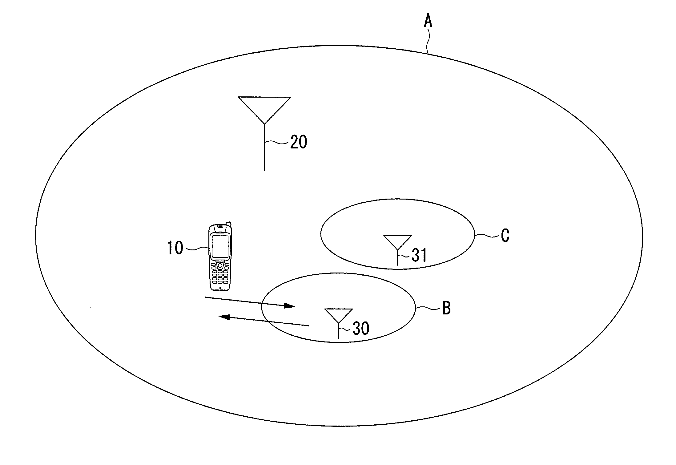
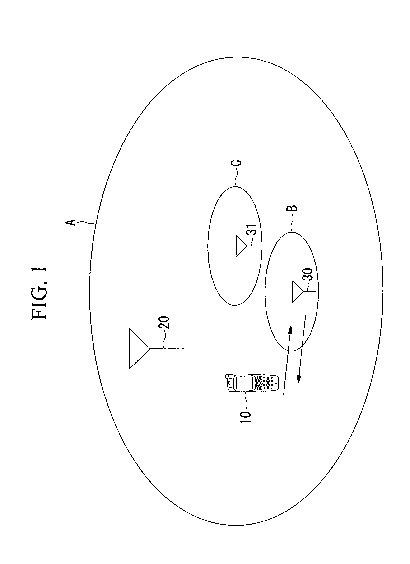
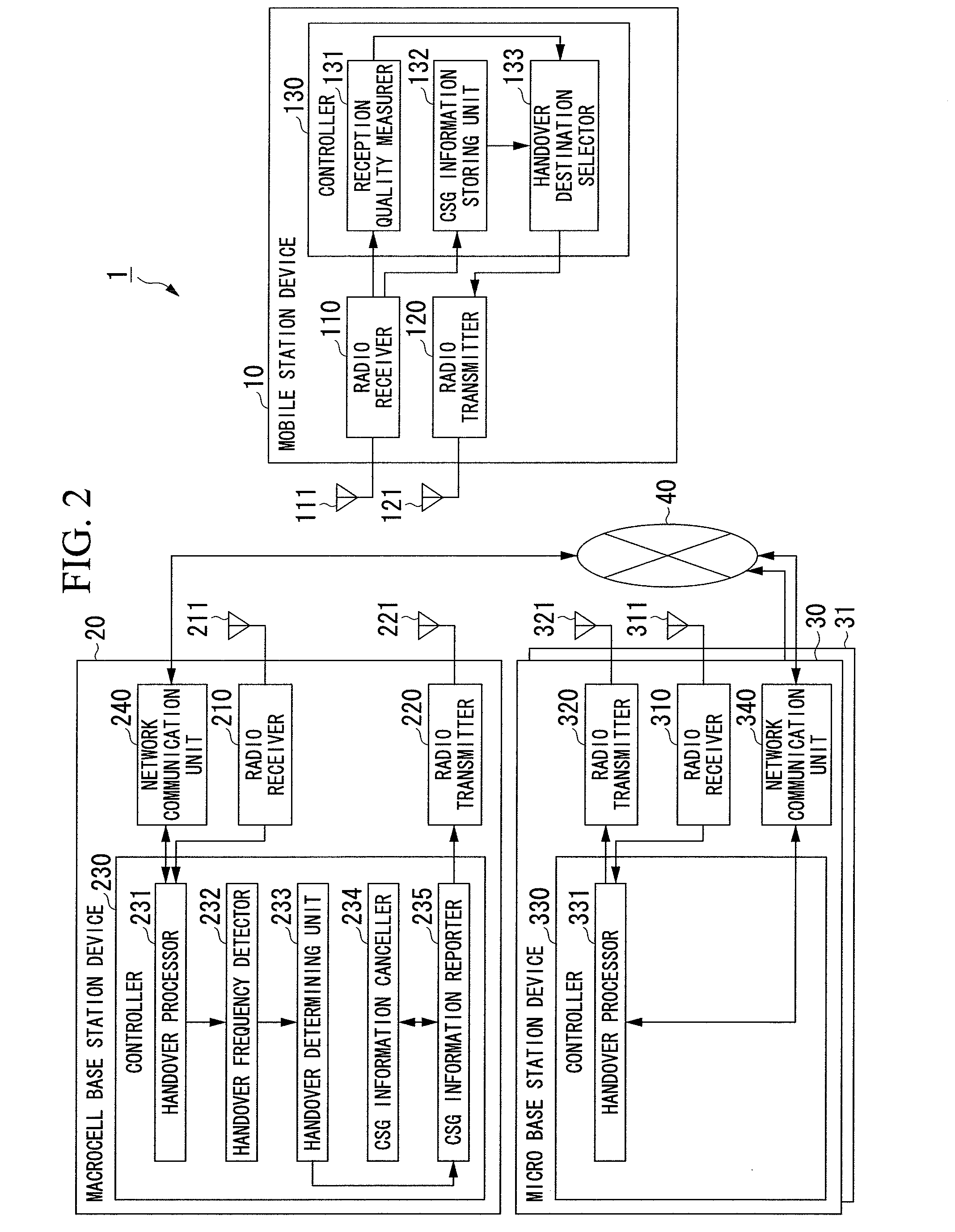
[0038]Hereinafter, a first embodiment of the present invention is explained with reference to the drawings. FIG. 1 is a conceptual diagram illustrating a configuration of a wireless communication system 1 according to the first embodiment of the present invention. As shown in FIG. 1, the wireless communication system 1 according to the first embodiment includes: a mobile station device 10; a macrocell base station device 20 providing broadband services; and micro base station devices 30 and 31.

[0039]In FIG. 1, the area in which the macrocell base station device 20 provides services is regarded as a macrocell A. Additionally, part of the area of the macrocell A is regarded as a CSG cell B that is the area in which the micro base station device 30 provides services. Similarly, part of the area of the macrocell A is regarded as a CSG cell C that is the area in which the micro base station device 31 provides services.

[0040]If the micro base station device 30 properly operates in the ser...

second embodiment

[0075]In the first embodiment, the number of handovers is measured by the macrocell base station device 20. In a second embodiment, a micro base station device 30a for a CSG cell counts the number of handovers, and reports handover number information to a macrocell base station device 20a through the network 40 such as a backhaul line, and reflects the handover number information on CSG information reported from the macrocell base station device 20a. Here, the micro base station device 30a for the CSG cell includes a timer C that counts a duration for which the number of handovers is counted. FIG. 5 is a diagram illustrating a state of cell arrangement for a wireless communication system 1a according to the second embodiment. As shown, in the second embodiment, part of the area of the macrocell A that is a cell served by the macrocell base station device 20a is regarded as the CSG cell B that is a cell served by the micro base station device 30a.

[0076]FIG. 6 is a schematic block di...

third embodiment

[0088]In the third embodiment, where the mobile station device 10 performs a handover between the macrocell base station device 20a and a micro base station device 30b for a CSG cell (Closed Subscriber Group) disposed in the macro cell, the mobile station device 10 reports, as reception level information, the reception level measured by the micro base station device 30b for the CSG cell to the macrocell base station device 20a through the network 40 such as a backhaul line, and thereby reflects the reception level information on CSG information to be reported from the macrocell base station device 20a.

[0089]FIG. 9 is a schematic block diagram illustrating a configuration of a wireless communication system 1b according to the third embodiment. The wireless communication system 1b includes: the mobile station device 10; the macrocell base station device 20a; and the micro base station device 30b. Similar to FIGS. 2 and 6, the mobile station device 10 includes: the radio receiver 110;...


PUM


Abstract

A wireless communication system includes: a macrocell base station device; a micro base station device serving a cell having a region including at least a part of a region of a cell served by the macrocell base station device; and a mobile station device. One of the macrocell base station device and the micro base station device includes a reporter configured to report, to the mobile station device, micro base station information indicating the micro base station device to which the mobile station device can perform a handover. The mobile station device includes a handover destination selector configured to select a handover destination based on the micro base station information reported. Thereby, a handover is prevented while preventing the processing load on the mobile station device.

Description

TECHNICAL FIELD[0001]The present invention relates to a wireless communication system and a handover method.[0002]Priority is claimed on Japanese Patent Application No. 2009-195710, filed Aug. 26, 2009, the content of which is incorporated herein by reference.BACKGROUND ART[0003]Regarding a wireless communication system providing services for CSG (Closed Subscriber Group) cells, the area of service provided by a micro base station for a CSG cell is smaller than the area of service provided by a macrocell base station. For this reason, if a mobile terminal in communication continues to move, and even if the mobile terminal once accesses the micro base station for the CSG cell, the mobile terminal moves out of the area of the service provided by the micro base station in no time, and therefore performs a handover from the micro base station for the CSG cell to the macrocell base station. Thereafter, if the mobile terminal returns to the original place, the mobile terminal performs a h...

Claims


Application Information

Patent Timeline
Patent Type & Authority Applications(United States)
IPC IPC(8): H04W36/34
CPCH04W36/0072H04W36/32H04W36/04
Inventor SAWADA, SHINICHIKOBAYASHI, HIROKAZUSUZUKI, SHIGETOSUZUKI, KOHKIYOSHIHARA, AKIO
Owner SHARP KK
Why Eureka
Try Eureka