Split-cycle engine

a split-cycle engine and compression-ignition technology, which is applied in the direction of combustion engines, fuel injection apparatus, charge feed systems, etc., can solve the problems of high mechanical stress, noise, and high pressure gradient in the combustion phase, and achieve the effect of low dust emissions

Active Publication Date: 2012-07-05
GREEN ENGINE CONSULTING
View PDF6 Cites 6 Cited by
  • Summary
  • Abstract
  • Description
  • Claims
  • Application Information

AI Technical Summary

Benefits of technology

[0011]It is a feature of the present invention to provide a compression-ignition “split-cycle” engine that causes low emissions of dust.
[0012]It is a further feature of the present invention to provide a compression-ignition engine that causes low emission of nitrogen oxides.
[0013]It is also a feature of the present invention to provide a compression-ignition engine that makes it possible to obtain high values of efficiency and of specific power.

Problems solved by technology

The peculiar combustion mode of said engines has the consequence of highly polluting emissions of carbonaceous dust and nitrogen oxides.
However in all these techniques, for controlling the combustion progress, it is necessary the presence in the cylinder of a high percentage of burnt gas, which limit the available specific power.
Other disadvantages, in species due to some of these techniques, are the high pressure gradient in the combustion phase, which involves both noise, and high mechanical stress.
Even if in the cited patent documents the possible application of the system to compression-ignition engines is cited, it is observed that this application is not feasible.
This would give rise to an unbearable thermal stress of the combustion-sided valves, The presence of the latter would cause also a low efficiency for pressure drop during the passage of the combustion gas through the valve.
Furthermore, in the engine described in the cited documents, as the combustion-sided opens a strong pressure difference is present between the compression cylinder and the expansion cylinder, with subsequent loss of efficiency owing to strong fluid dynamic loss.

Method used


Image

  • Split-cycle engine
  • Split-cycle engine
  • Split-cycle engine

Examples


Embodiment Construction

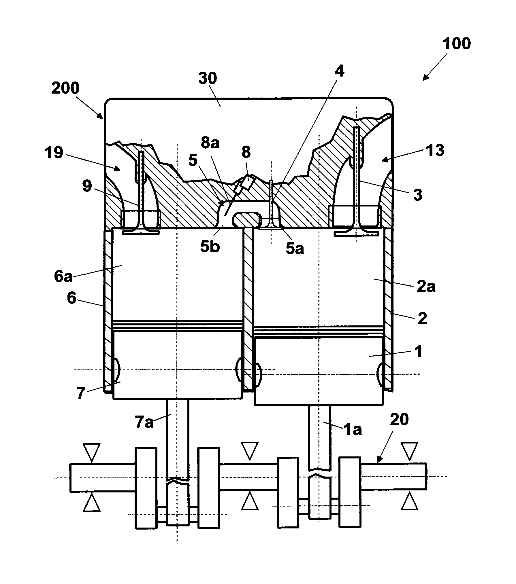
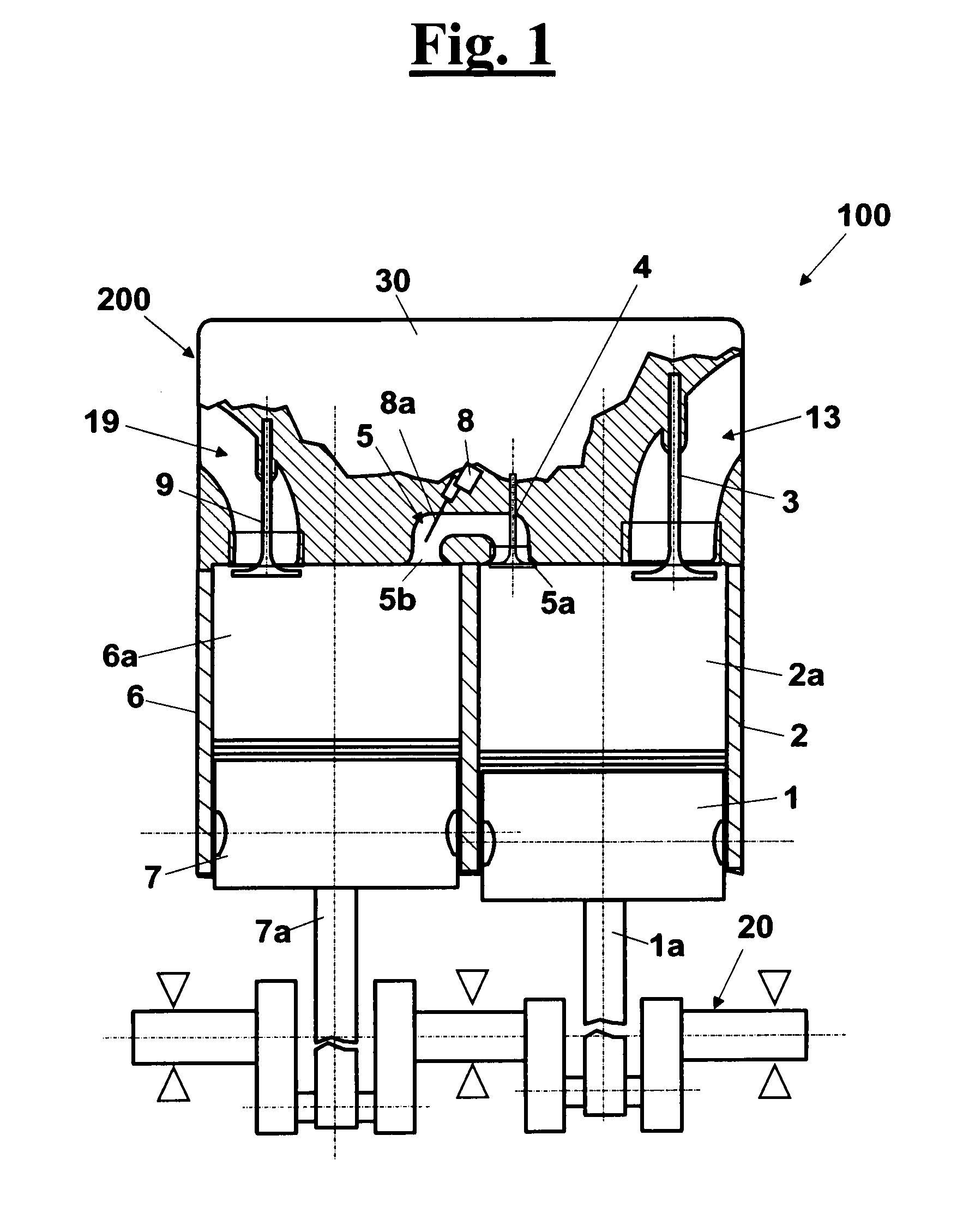
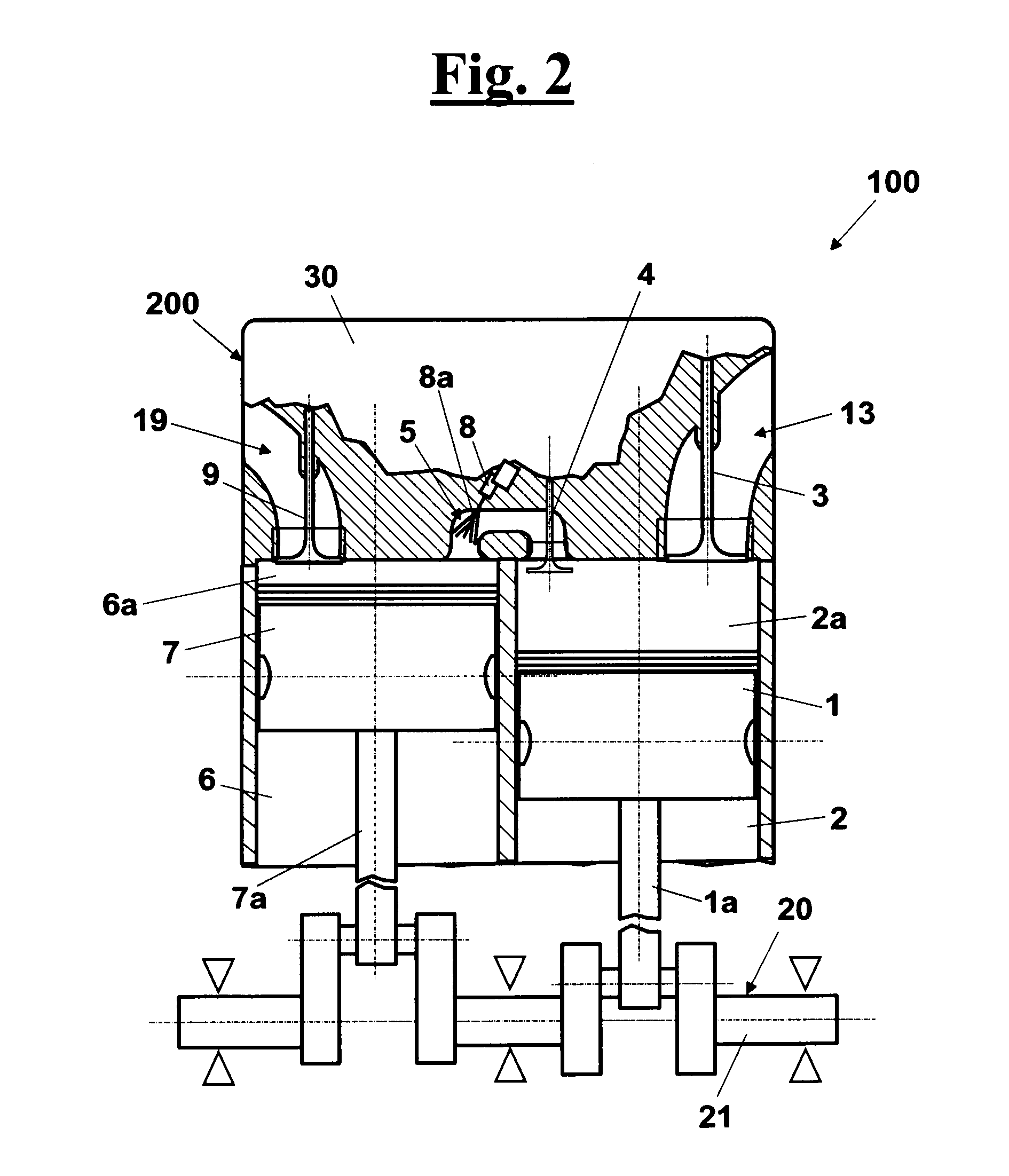
[0055]With reference to FIGS. 1 and 2, a compression-ignition “split-cycle” engine 100, according to the invention, comprises a cylinder block 200 with an expansion cylinder 6 associated with a relative expansion piston 7 that is adapted to move alternatively between a top dead center (ETDC) and a bottom dead center (EBDC) in expansion cylinder 6 by means of a crankshaft mechanism 20. In particular, crankshaft mechanism 20 causes a predetermined position of expansion piston 7 to correspond always to a predetermined crankshaft angle. In particular, as shown in FIG. 3 the ETDC of expansion piston 7 corresponds to a crankshaft angle of 0°.

[0056]Furthermore, cylinder block 200 comprises a compression cylinder 2 associated with a relative compression piston 1 that is adapted to move alternatively between a top dead center (CTDC) and a bottom dead center (CBDC) in compression cylinder 2 according to a predetermined delay with respect to the crankshaft angle of the expansion piston 7. Comp...


PUM


Abstract

A compression-ignition “split-cycle” engine (100) comprises: a cylinder block (200) with an expansion cylinder (6) having an expansion piston (7) that is adapted to move alternatively between a top dead center (ETDC) and a bottom dead center (EBDC) by a crankshaft mechanism (20) that causes a predetermined position of the expansion piston (7) to correspond to a predetermined crankshaft angle; a compression cylinder (2) having a compression piston (1) that is adapted to move alternatively between a CTDC and a CBDC according to a predetermined angular phase shift in delay to the expansion piston (7); a cylinder head (30) that closes the cylinders and comprises a crossover passageway (5) with an opening (5a) in constant communication towards compression cylinder (2) and an opening (5b) having a transfer valve (4) towards expansion cylinder (6), an intake valve (3) and a exhaust valve (9); a means for opening / closing the transfer valve (4); a means for opening / closing exhaust valve (9) at predetermined moments of the alternative cycle of the pistons, and a fuel injector (8) in the crossover passageway (5). The opening movement of the transfer valve (4) is carried out in advance 20° or more of crankshaft angle with respect to the crankshaft angle of the ETDC, such that from the opening instant up to reaching the ETDC there is a substantial equalization of pressure between the cylinders, such that between the ETDC and the CTDC a transfer occurs of the comburent fluid between the two cylinders, and such that injector (8) injects the fuel (8a) starting from the achievement of the ETDC.

Description

FIELD OF THE INVENTION[0001]The present invention relates to a “split-cycle” compression-ignition engine, with introduction of fuel and comburent fluid in the expansion cylinder in the combustion phase.DESCRIPTION OF THE PRIOR ART[0002]As well known, conventional compression-ignition engines carry out the cycle in a single cylinder, in which firstly there is an intake of air, which is then compressed; then fuel is injected an ignited owing to the high temperature reached by air owing to the compression; the steps follow of expansion and of exhaust. The peculiar combustion mode of said engines has the consequence of highly polluting emissions of carbonaceous dust and nitrogen oxides.[0003]Various solutions have been proposed for reducing said emissions and are based on improvements of the injection system and also on particular strategies of intake and mixture of the fuel with air, according to the principle of homogeneous combustion, among which known techniques such as HCCl, PCCl, ...

Claims


Application Information

Patent Timeline
Patent Type & Authority Applications(United States)
IPC IPC(8): F02B41/06F02B33/40F02B1/12
CPCF02B33/22F02M69/046F02B41/06F02B37/00Y02T10/12F02B37/04
Inventor GENTILI, ROBERTOROSSI, RICCARDOMUSU, ETTORE
Owner GREEN ENGINE CONSULTING
Why Eureka
Try Eureka