Dust emission reduction during metal casting

a technology of metal casting and dust emission reduction, applied in the direction of drying machines with progressive movement, furnaces, lighting and heating apparatus, etc., can solve the problem of rare possibility, and achieve the effect of reducing the emission of diffuse dus

Inactive Publication Date: 2014-11-13
PAUL WURTH SA
View PDF3 Cites 2 Cited by
  • Summary
  • Abstract
  • Description
  • Claims
  • Application Information

AI Technical Summary

Benefits of technology

[0009]The invention provides a method and a device to reduce diffuse dust emissions during the casting of a metal or slag and in particular, but not exclusively, in integrated steel plants. It is a further object of the invention to propose a solution which is implementable in known metal casting apparatuses without requiring complex and expensive modifications to this well-proven and established techniques.
[0010]In order to overcome the above-mentioned problem, the present invention proposes, in a first aspect, a method for reducing dust emissions during the casting of a molten metal or slag in the form of ingots with an apparatus comprising an endless conveyor having a plurality of casting molds with upper open tops and which endless conveyor is arranged to move said casting molds in a first section from a casting station to a discharge station and in a second section back to the casting station. In fact, the method comprises the following steps:

Problems solved by technology

In practice however, this is rarely possible due to the size of the pigs.
Although graphite kish formation is a particular issue during pig iron casting, the dust formation during casting of other metals or slags may also be a concern.

Method used


Image

  • Dust emission reduction during metal casting
  • Dust emission reduction during metal casting
  • Dust emission reduction during metal casting

Examples


Embodiment Construction

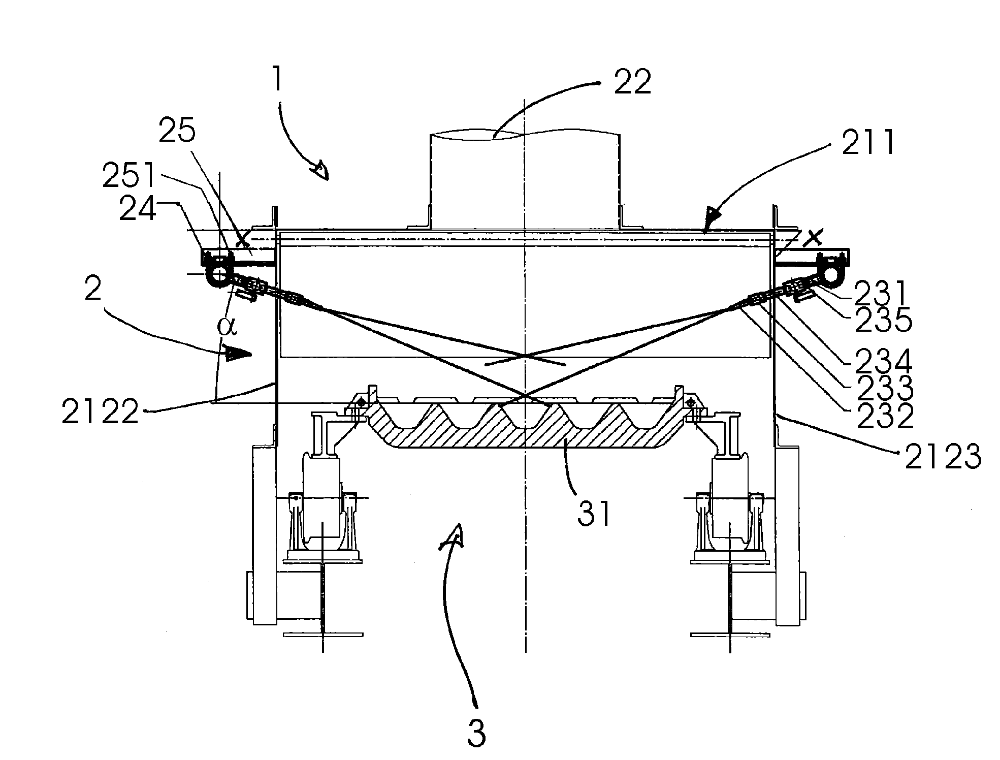
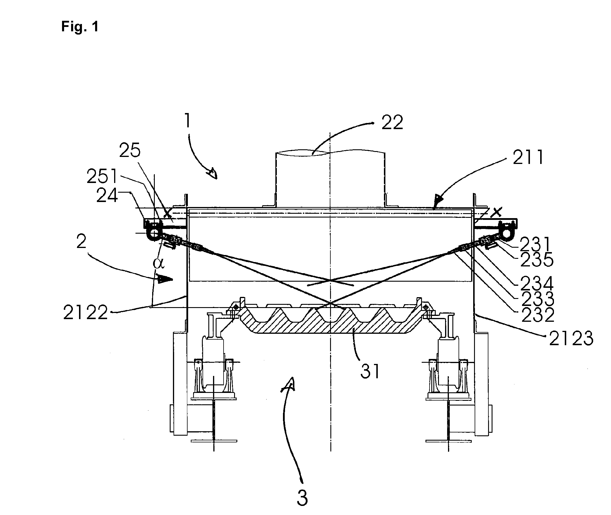
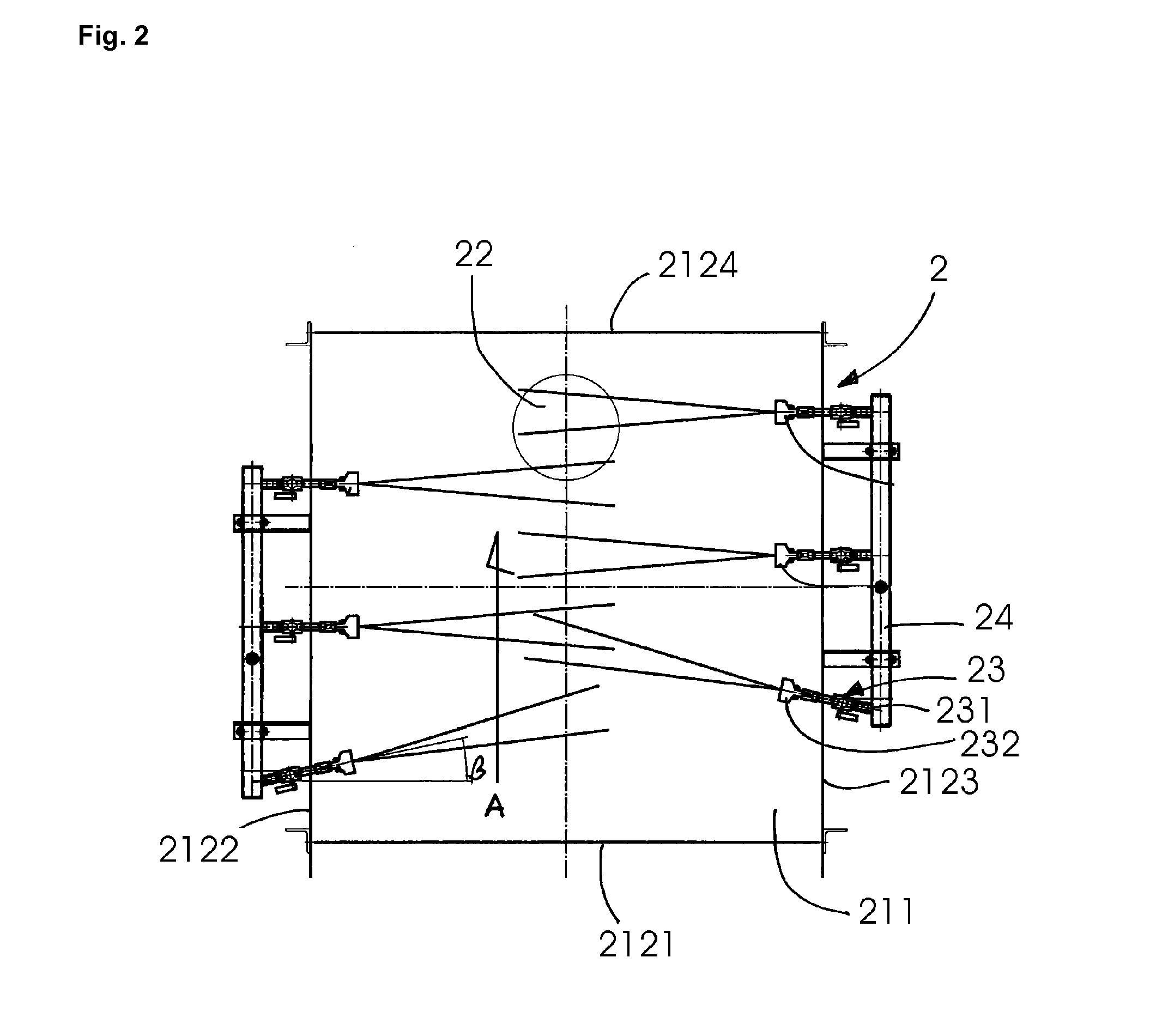
[0053]FIG. 1 shows a cross sectional view of a preferred embodiment of a metal or slag casting apparatus 1. The cross section represented by FIG. 1 is located in the first section of the endless conveyor 3 between the casting station (not shown) to the discharge station (not shown). FIG. 2 corresponds to a top view of section X-X in FIG. 1, but of the dust control device only (conveyor not shown).

[0054]In this first section, above the endless conveyor 3 having a plurality of casting molds 31, a dust control device 2 having a casing 21 comprising a top cover 211 and peripheral sidewalls 212 is provided. The peripheral sidewalls comprise, relative to the conveying direction A (see FIG. 2), a front part 2121, two lateral parts 2122, 2123 and a back part 2124.

[0055]A plurality of blowing nozzles 23 (of which two are shown in FIG. 1) are arranged such that their outlets 232 are located within the casing 2 at an angle α with respect to the top of the casting molds 31. The outlet 232 of th...


PUM

PropertyMeasurementUnit
angleaaaaaaaaaa
angleaaaaaaaaaa
angleaaaaaaaaaa

Abstract

A method for reducing dust emissions in a metal or slag casting apparatus, as well as a metal or slag casting apparatus allowing reducing dust emissions, comprising an endless conveyor having a plurality of casting moulds with upper open tops and which endless conveyor is arranged to move said casting moulds in a first section from a casting station to to the casting station, the method comprising (a) providing a casing forming a bottomless box over at least part of the first section of the endless conveyor, (b) injecting within said casing a gas on the surface of the mould with an angle sufficient to blow off loose, solid particles, such as graphite flakes, formed at the surface of the metal, during early stages of the cooling down and to start the solidification of a superficial layer of metal or slag, (c) extracting the gas and the solid particles by suction from within said casing.

Description

TECHNICAL FIELD[0001]The present invention generally relates to reducing dust emission during hot metal or slag casting, in particular in metal casting machines and especially during pig (iron) casting.BACKGROUND ART[0002]As it is well known within the art, liquid hot metal is either poured directly out of the bottom of the blast furnace through a trough into a ladle car for transfer to the steel mill. If it cannot be processed directly, it is cast in the form of ingots, so-called pigs, for storage or for further transport.[0003]Nowadays, so-called pig casting machines or apparatuses are used for manufacturing said pigs of pig iron. They conventionally comprise a casting station, at least one endless conveyor with a plurality of casting molds, as well as a removal station at the discharge point of the endless conveyor.[0004]When reaching the casting station, the (empty) casting mound is filled with liquid hot metal and is conveyed to the discharge point. The conveying path and / or co...

Claims


Application Information

Patent Timeline
Patent Type & Authority Applications(United States)
IPC IPC(8): B22D45/00B22D5/04
CPCB22D45/005B22D5/04
Inventor LESSMANN, HANS JUERGENBOTH, INGOHOUBART, MICHELKINZEL, KLAUS PETERNOUAILLE-DEGORCE, GILLES
Owner PAUL WURTH SA
Why Eureka
Try Eureka