
Slow-acting on/off valve

Active Publication Date: 2012-07-05
FUJIKURA COMPOSITES INC
View PDF12 Cites 6 Cited by
  • Summary
  • Abstract
  • Description
  • Claims
  • Application Information

AI Technical Summary

Benefits of technology

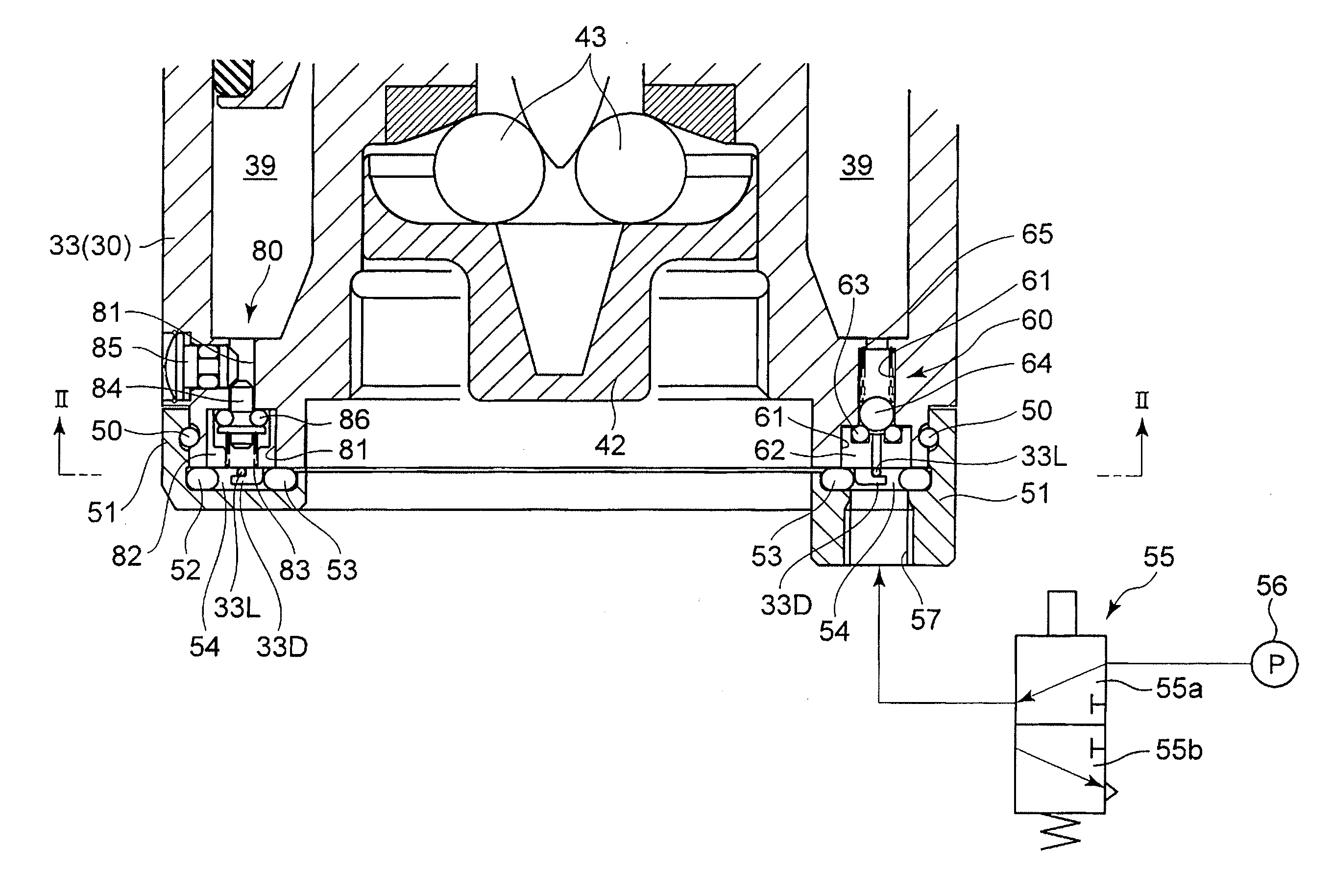
[0011]According to the present invention, by an extremely simple structure in which a manifold is formed separately from a valve-opening pressure chamber that makes the actuating member move in the valve-opening direction and in which three valves: a pressure regulation valve, a flow regulation valve and an exhaust valve, are installed between the valve-opening pressure chamber and the manifold, a slow-acting ON / OFF valve can be achieved which is superior in responsiveness, from when a valve-opening signal (air pressure) is given until a valve-opening operation is carried out, and which makes the valve-opening operation performed slowly.

Problems solved by technology

Conventionally, pneumatic-operated ON / OFF valves used for high-pressure gas cylinders have been satisfactorily achieved in terms of automatization of the valve-opening / closing operation but have not satisfactorily complied with the demand for a slowing-down of the valve opening speed.

Method used


Image

  • Slow-acting on/off valve
  • Slow-acting on/off valve
  • Slow-acting on/off valve

Examples


Embodiment Construction

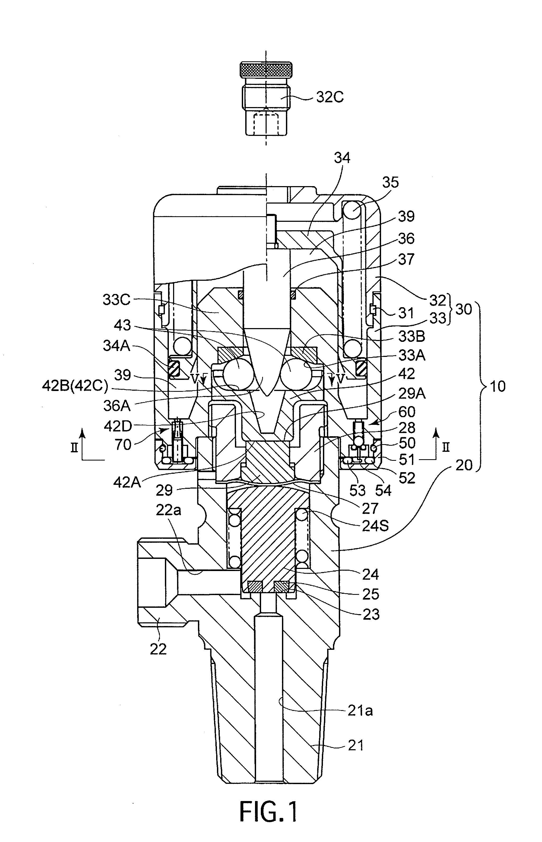
[0019]As shown in FIG. 1, the present embodiment of a slow-operating ON / OFF valve 10 is provided with a gas cylinder head 20, which is detachably attached to a high-pressure tank (gas cylinder), and a bonnet (housing / cylinder) 30.

[0020]The gas cylinder head 20 is provided with a screw-in connecting projection 21, which screws into the high-pressure tank, and a threaded-tap projection 22. A flow passage 21a and a flow passage 22a which are communicatively connected to each other in a mutually orthogonal positional relationship are formed in the screw-in connecting projection 21 and the threaded-tap projection 22, respectively. An annular valve seat 23 is formed in the gas cylinder head 20 to be positioned concentrically with the flow passage 21a in a passageway portion between the flow passage 21a and the flow passage 22a, and an ON / OFF valve body 24 which comes into contact with and moves away from the annular valve seat 23 to close and open the flow passage is supported to be slida...


PUM


Abstract

Disclosed is a slow-acting ON / OFF valve which includes a valve-opening pressure chamber that makes an actuating member (which actuates a valve body that comes into contact with and moves away from a valve seat to close and open a flow passage) move in a valve-opening direction against a spring biasing force in a valve-closing direction, and supplies air to the valve-opening pressure chamber, in minute increments, via a flow rate regulation valve. In this slow-acting ON / OFF valve, the dead time from the receipt of a valve-opening signal to the commencement of a valve-opening operation is short. A manifold is provided independently of the valve-opening pressure chamber. Between the valve-opening pressure chamber and the manifold, the following three valves are provided: a pressure regulation valve which allows air to flow into the valve-opening pressure chamber from the manifold until pressure in the valve-opening pressure chamber reaches a predetermined reserve pressure and which is closed upon the pressure in the valve-opening pressure chamber reaching the reserve pressure; a flow rate regulation valve which supplies air to the valve-opening pressure chamber from the manifold, in minute increments, after the pressure in the valve-opening pressure chamber reaches the reserve pressure; and an exhaust valve which rapidly discharges air in the valve-opening pressure chamber to the manifold upon pressure in the manifold dropping below the pressure in the valve-opening pressure chamber and is thereafter closed.

Description

TECHNICAL FIELD[0001]The present invention relates to a slow-acting ON / OFF valve (normally-closed valve) which is superior in responsiveness, from when a valve-opening signal (air pressure) is given until a value-opening operation is carried out, even though the valve-opening operation itself is slow.BACKGROUND ART[0002]Conventionally, pneumatic-operated ON / OFF valves used for high-pressure gas cylinders have been satisfactorily achieved in terms of automatization of the valve-opening / closing operation but have not satisfactorily complied with the demand for a slowing-down of the valve opening speed. For instance, when certain types of gases are mixed in a reaction chamber, it is sometimes required that the gasses to be mixed are supplied into the reaction chamber as slow as possible. Applicants including the applicant of the present invention and inventors including the inventor of the present invention have proposed a slow-acting ON / OFF valve capable of satisfying such a demand an...

Claims


Application Information

Patent Timeline
IPC IPC(8): F16K31/122F16K24/04
CPCF16K1/307F16K1/305F16K24/04F16K31/122F17C7/00F17C13/04
Inventor EJIRI, TAKASHI
Owner FUJIKURA COMPOSITES INC
Learn More