Electrowetting display apparatus and dye composition for electorwetting display
Inactive Publication Date: 2013-11-14
FUJIFILM CORP
View PDF7 Cites 8 Cited by
Summary
Abstract
Description
Claims
Application Information
AI Technical Summary
This helps you quickly interpret patents by identifying the three key elements:
Problems solved by technology
Method used
Benefits of technology
Benefits of technology
The present invention is aimed at providing an electrowetting display apparatus and a dye composition for electrowetting display that can display images with high density, excellent responsiveness, and prevent image disturbance caused by a backflow phenomenon. This technology has garnered attention as a potential replacement for paper and is being heralded as a promising display option.
Problems solved by technology
However, dyes sometimes have poor solubility in a nonpolar solvent constituting an oil phase, and therefore it is difficult to increase the concentration of the coloring material to a level suitable for an image display, while maintaining good display properties.
However, if the dye amount is too large, the operating sensitivity (responsiveness) of the oil in response to a voltage applied is decreased, and the image formation property tends to deteriorate significantly.
Method used
Image
Click on the blue label to locate the original text in one second.
Reading with bidirectional positioning of images and text.
Examples
example 1
Preparation of Dye Ink
[0216]Using the surfactants listed below, argon gas to which the surfactants were added at a rate of 1 mass % as shown in the following Table 1, respectively, was bubbled into n-decane, to thereby prepare an n-decane solution having a dissolved oxygen concentration of 10 ppm or less. The prepared n-decane solution was subjected to a heat-treatment at 50° C. and left standing at room temperature for 12 hours. After that, to the thus-treated n-decane solution, the dye E-11 mentioned below was added in an amount specified in the following Table 1 and Table 2 (40 mass % or 10 mass %). In this manner, plural kinds of dye inks were prepared.
[0240]A dye ink was prepared, a test cell was produced, and evaluations were carried out, respectively, in the same manner as in Example 1, except that an ink having dissolved the following methine dye F-1 at 30 mass % instead of the dye E-11 in Example 1 was used. The evaluation results are shown in the following Table 5.
TABLE 5[Dye concentration: 30 mass %]ResponsivenessAreaResponsereductiontimeBackflowSurfactantrate [%][msec][%]ODRemarks1No55200msec to 1 sec1801.6Comparativeaddition2K-130200msec to 1 sec1201.6PresentinventionIn Table 5, an area reduction rate of 100% indicates a state without reduction.
[0241]As shown in Table 5, it has been confirmed that the responsiveness and the backflow were improved when the dye ink according to the present invention was used.
example 3
[0242]A dye ink was prepared, a test cell was produced, and evaluations were carried out, respectively, in the same manner as in Example 1, except that an ink having dissolved the following anthraquinone dye G-1 at 20 mass % instead of the dye E-11 in Example 1 was used. The evaluation results are shown in the following Table 6.
TABLE 6[Dye concentration: 20 mass %]ResponsivenessAreaResponsereductiontimeBackflowSurfactantrate [%][msec][%]ODRemarks1No40200msec to 1 sec2200.9Comparativeaddition2K-130200msec or less1400.9InventiveIn Table 6, an area reduction rate of 100% indicates a state without reduction.
[0243]As shown in Table 6, it has been confirmed that the responsiveness and the backflow were improved when the dye ink according to the present invention was used.
PUM
Property
Measurement
Unit
Percent by mass
aaaaa
aaaaa
Percent by mass
aaaaa
aaaaa
Structure
aaaaa
aaaaa
Abstract
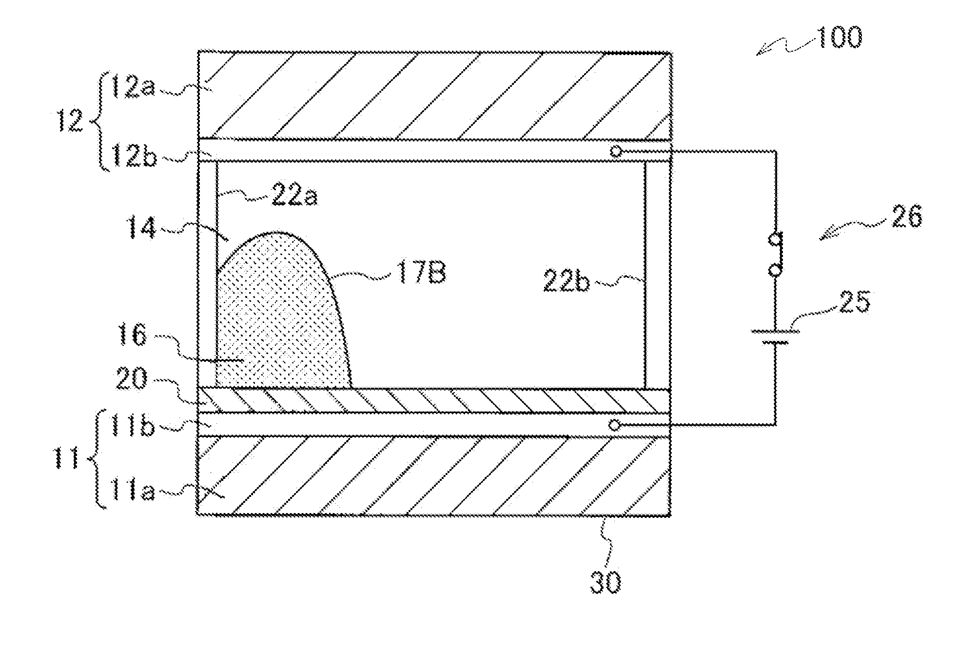
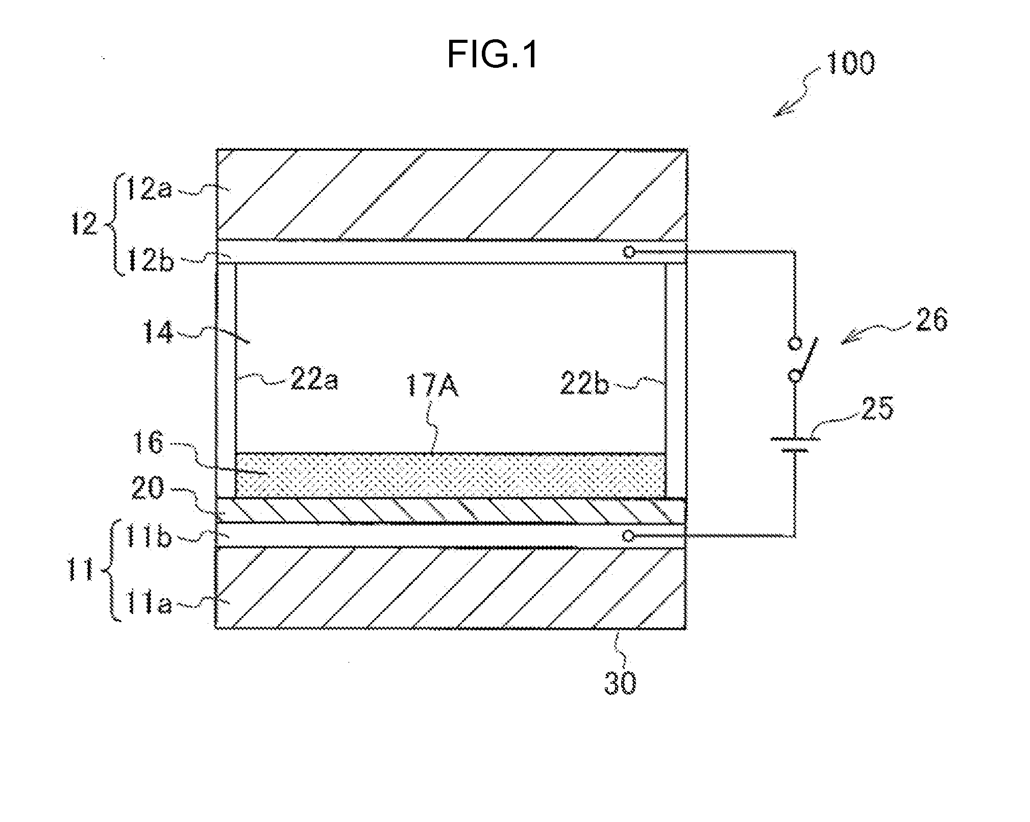
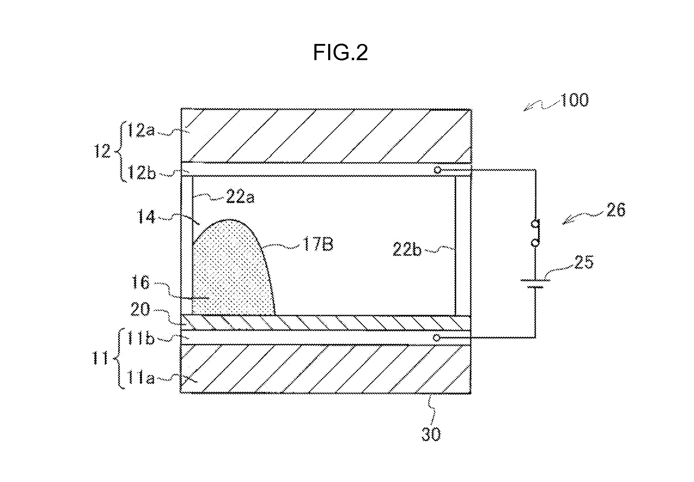
An electrowetting display apparatus is provided, which has a display unit including: a first substrate at least one surface of which is electroconductive; a second substrate arranged to face the electroconductive surface of first substrate; a hydrophobic insulation film arranged on the electroconductive surface of first substrate; a non-electroconductive oil provided between the hydrophobic insulation film and second substrate movably on the hydrophobic insulation film and containing a nonpolar solvent, a dye in a content of 10 mass % or higher with respect to the total mass of oil, and a nonionic surfactant; and an electroconductive hydrophilic liquid provided between the hydrophobic insulation film and second substrate so as to contact the oil; wherein an image is displayed by applying a voltage between the hydrophilic liquid and electroconductive surface of first substrate for changing the shape of an interface between the oil and hydrophilic liquid.
Description
CROSS-REFERENCE TO RELATED APPLICATION[0001]This application claims priority under 35 USC 119 from Japanese Patent Application No. 2012-108404 filed on May 10, 2012, and Japanese Patent Application No. 2013-054289 filed on Mar. 15, 2013, the disclosures of which are incorporated by reference herein.BACKGROUND OF THE INVENTION[0002]1. Field of the Invention[0003]The present invention relates to an electrowetting display apparatus and a dye composition for electrowetting display.[0004]2. Description of the Related Art[0005]Optical devices have been investigated, which are each equipped with a cell containing two or more kinds of liquids that are not miscible with each other (for example, the two liquids being an oil and a hydrophilic liquid), and which are operated (or driven) by application of a voltage. Examples of such optical devices that are well-known include an optical shutter, a varifocal lens, an image display apparatus, and the like. In particular, a technology utilizing an ...
Claims
Application Information
Patent Timeline
Application Date:The date an application was filed.
Publication Date:The date a patent or application was officially published.
First Publication Date:The earliest publication date of a patent with the same application number.
Issue Date:Publication date of the patent grant document.
PCT Entry Date:The Entry date of PCT National Phase.
Estimated Expiry Date:The statutory expiry date of a patent right according to the Patent Law, and it is the longest term of protection that the patent right can achieve without the termination of the patent right due to other reasons(Term extension factor has been taken into account ).
Invalid Date:Actual expiry date is based on effective date or publication date of legal transaction data of invalid patent.

