High-pressure fuel pump

Inactive Publication Date: 2015-04-09
TOYOTA JIDOSHA KK
View PDF8 Cites 10 Cited by
  • Summary
  • Abstract
  • Description
  • Claims
  • Application Information

AI Technical Summary

Benefits of technology

[0027]According to the above configuration, the suction valve seat, the partition wall, and the one end of the cylindrical member can easily be joined to the holder member in this order, and the fuel introducing chamber can easily be defined by t

Problems solved by technology

However, it has been concerned that pressurization failure occurs in the conventional high-pressure fuel pump as described above when the conventional high-pressure fuel pump is used in such a condition that an engine of a vehicle is temporarily stopped while being soaked with the fuel at a high temperature and is then restarted.
Thus, parts and control are required as a measure

Method used


Image

  • High-pressure fuel pump
  • High-pressure fuel pump
  • High-pressure fuel pump

Examples


Example

[0038]A description will hereinafter be made on a preferred embodiment of the present invention with reference to drawings.

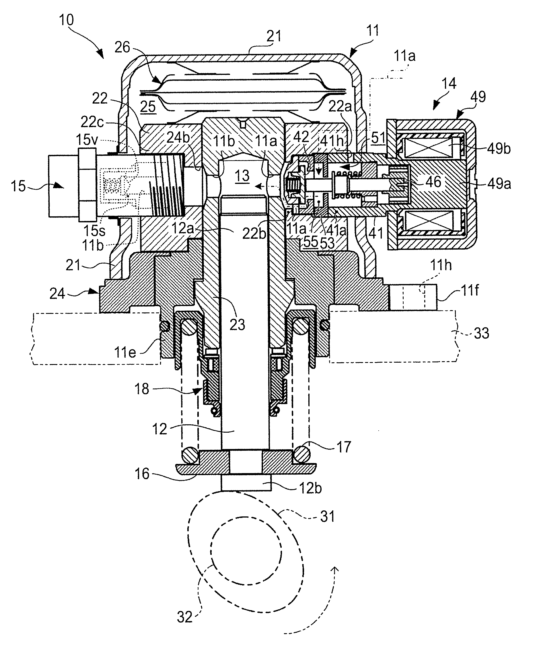
[0039](Embodiment) FIG. 1 is a schematic block diagram of a configuration of a high-pressure fuel pump according to the embodiment of the present invention,

[0040]First, the configuration will be described.

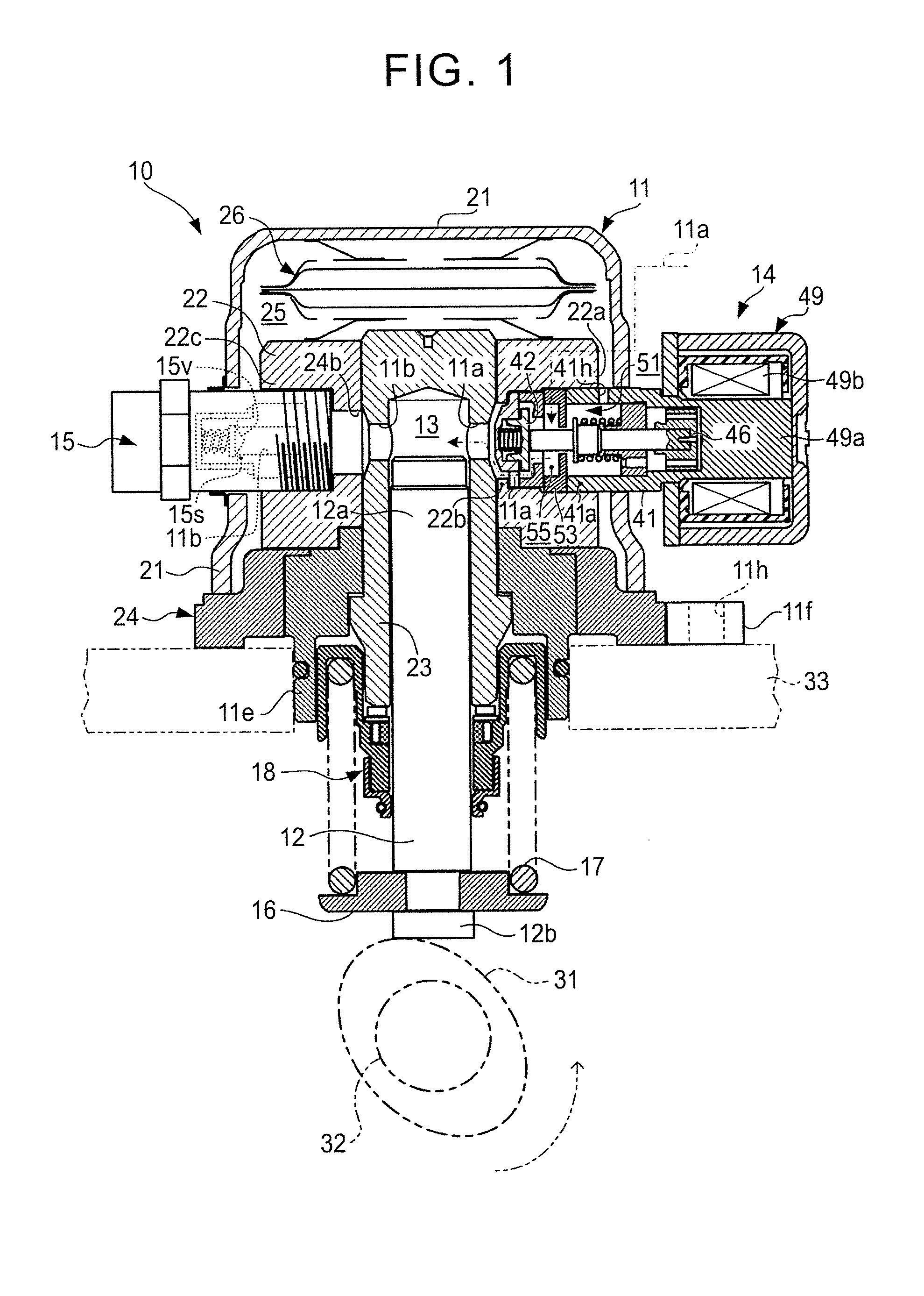
[0041]FIG. 1 to FIG. 3 show the configuration of the high-pressure fuel pump according to the embodiment of the present invention.

[0042]A high-pressure fuel pump 10 of this embodiment is installed in an internal combustion engine that is mounted in a vehicle, for example, a multi-cylinder gasoline engine of cylinder injection type or dual injection type (hereinafter simply referred to as an engine), and is of plunger pump type that pressurizes fuel of the engine to high pressure and discharge the pressurized fuel. Needless to say, the high-pressure fuel pump of the present invention can be applied to an engine other than the gasoline engine that uses fuel with ...


PUM


Abstract

A high-pressure fuel pump includes a pump housing, a pressurizing member, a suction valve seat, a suction valve body, and a suction valve chamber. The suction valve seat includes a first projected wall section that is projected to an upper side in a vertical direction. The pump housing includes a second projected wall section that is directed to the upper side in the vertical direction. A height of the lowest position in a portion of the second projected wall section that is projected to the upper side in the vertical direction is higher than a height of the lowest position in a portion of the first projected wall section that is projected to the upper side in the vertical direction. A first initial fuel pool is provided on an downstream side of the second projected wall section and on the upstream side of the suction valve seat.

Description

INCORPORATION BY REFERENCE[0001]The disclosure of Japanese Patent Application No. 2013-210144 filed on Oct. 7, 2013 including the specification, drawings and abstract is incorporated herein by reference in its entirety.BACKGROUND OF THE INVENTION[0002]1. Field of the Invention[0003]The present invention relates to a high-pressure fuel pump and in particular to a high-pressure fuel pump that forms a fuel pool on a suction side in a fuel pressurizing chamber.[0004]2. Description of Related Art[0005]As a high-pressure pump that pressurizes fuel and discharges the pressurized fuel, that is, a high-pressure fuel pump, a fuel pump has been known that pressurizes fuel of an internal combustion engine for running a vehicle (hereinafter referred to as an engine) to a such a degree that the fuel can be injected into a cylinder.[0006]Such a high-pressure fuel pump tends to form a fuel pool with a damper on an upstream side (a suction side) of a fuel pressurizing chamber in order to allow inter...

Claims


Application Information

Patent Timeline
IPC IPC(8): F02M59/46F02M59/42
CPCF02M59/42F02M59/462F02M59/367F02M59/447F02M59/464F02M2200/40
Inventor KATO, YOSHIKAZU
Owner TOYOTA JIDOSHA KK
Why Eureka
Try Eureka