Electronic lock with power failure control circuit

Active Publication Date: 2012-07-05
SARGENT MANUFACTURING CO INC
View PDF36 Cites 60 Cited by
  • Summary
  • Abstract
  • Description
  • Claims
  • Application Information

AI Technical Summary

Benefits of technology

[0024]In another aspect of the invention, the microcontroller prevents execution of the microcontroller executable instructio

Problems solved by technology

Regardless of the source of power, however, there is some risk that it will fail.
When the power source of an electronic lock begins to fail, memory storage may become corrupted during any attempt to write to storage, wireless or wired communication may become disrupted, and other electronic lock functions may fail to operate correctly.
Ultimately, in a power fail condition, the lock actuator will be una

Method used


Image

  • Electronic lock with power failure control circuit
  • Electronic lock with power failure control circuit
  • Electronic lock with power failure control circuit

Examples


Embodiment Construction

)

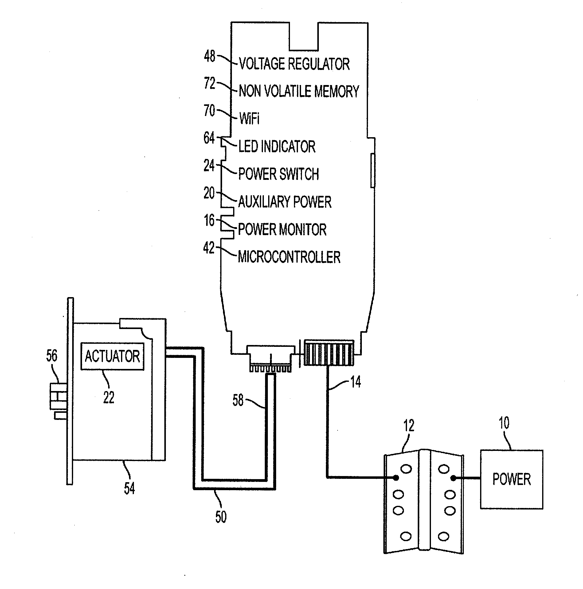
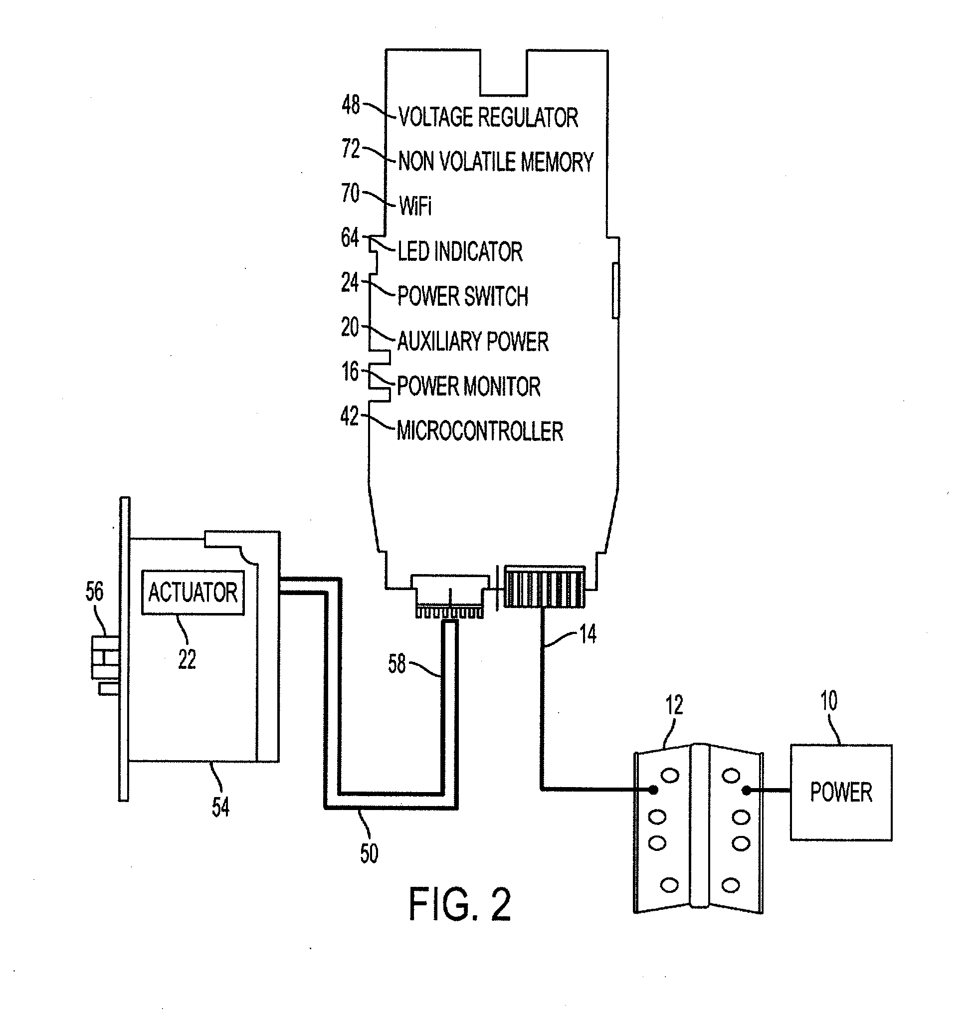
[0067]In describing the preferred embodiment of the present invention, reference will be made herein to FIGS. 1-4 of the drawings in which like numerals refer to like features of the invention.

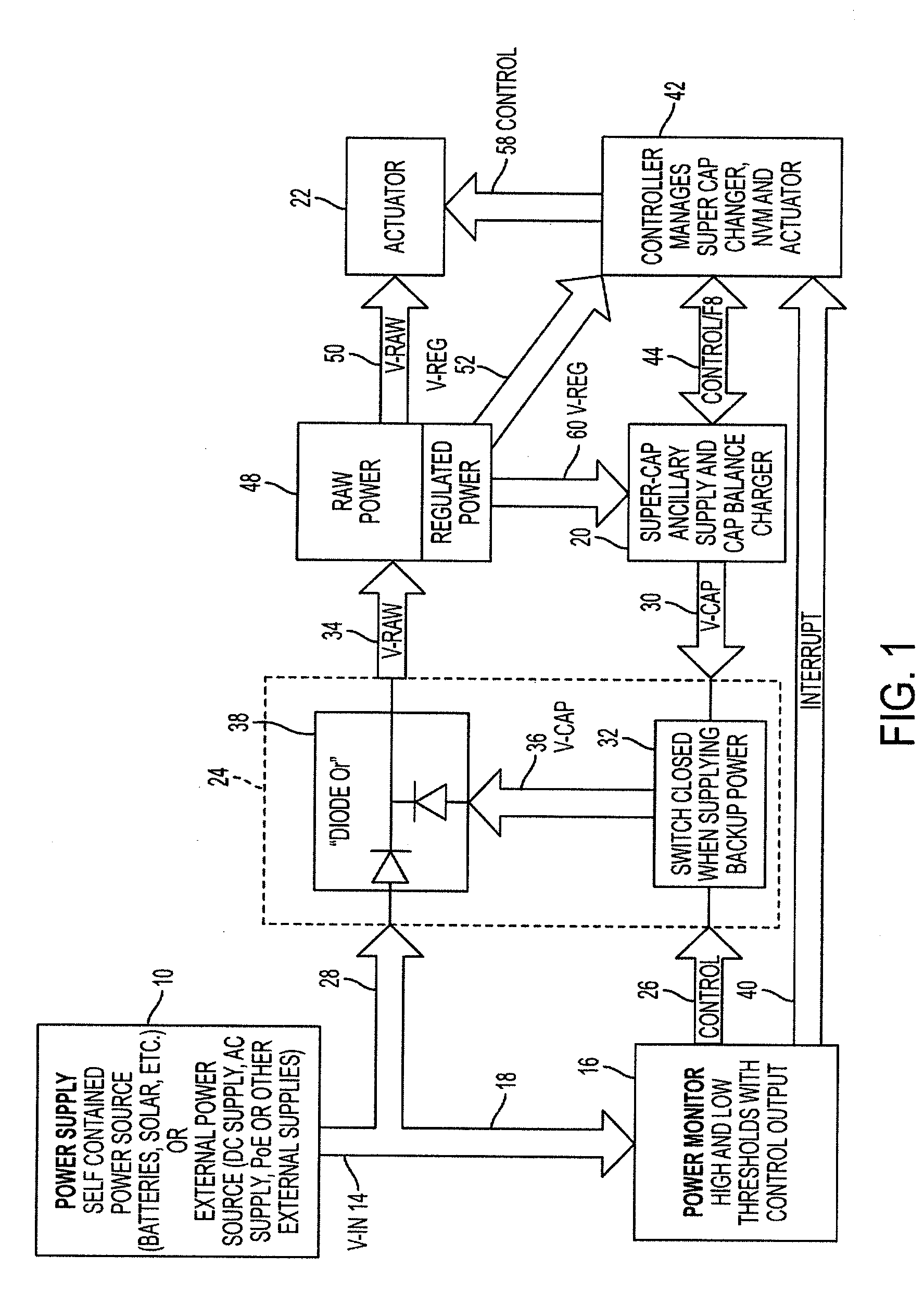
[0068]Broadly stated, an electronic lock with power failure control has been invented wherein a microcontroller receives inputs from a power monitor circuit to detect a decrease in power supply voltage (a power fail condition) and switches to supercapacitors as an auxiliary power source. The microcontroller controls a charging circuit to keep the supercapacitors charged. Once the microcontroller detects that the supercapacitors are fully charged, it enables setting of a power failure interrupt.

[0069]When the power monitor circuit detects a power failure condition, it sets the power failure interrupt and switches power from primary power to auxiliary power (available from the supercapacitors). When the microcontroller detects that the power failure interrupt has been set, it turns off circuit ...


PUM


Abstract

An electronic lock with power failure control circuit includes a lock mechanism having a latchbolt movable between extended and a retracted positions and an electrically powered lock actuator to lock and unlock the latchbolt. The power failure control circuit includes a microcontroller and the lock is connected to a primary power source and an auxiliary power source, preferably supercapacitors and charger that can be turned on by the microcontroller and off when the charger signals a full charge. A power monitor circuit detects low voltage on the primary power supply and sets a power failure interrupt causing the microcontroller to execute power failure instructions that control the actuator so that the lock is placed into a desired locked or unlocked final state during the power failure. upon detection of the return of good power, the system resets the lock.

Description

BACKGROUND OF THE INVENTION[0001]1. Field of the Invention[0002]This invention relates to electronic locks and to control circuits for such locks that operate when power fails or when the power supply voltage decreases. More specifically, this invention relates to power failure control circuits that operate to set a desired locked or unlocked status for the lock during the power failure period and to ensure proper startup and lock operation after power is restored.[0003]2. Description of Related Art[0004]Electronic locks are widely used in hotels, public buildings, prisons and commercial establishments as well as in high-end residential installations to provide sophisticated operational features. Such features may include electronic logging of lock operation, remote control of lock function, access authorization, indications of unauthorized break-in attempts and other lock and security related features.[0005]Locks of this type typically include an electromechanical lock actuator to ...

Claims


Application Information

Patent Timeline
IPC IPC(8): G05B23/02E05B47/00
CPCE05B47/00E05B2047/0087E05B2047/0059E05B2047/0057Y10T70/7113Y10T292/1014E05B47/02E05B49/00G05B23/02E05B47/0001E05C1/08G05B19/042
Inventor BRYLA, MARKMORSE, STEVEWREN, CHRIS
Owner SARGENT MANUFACTURING CO INC
Why Eureka
Try Eureka