Respiratory effect reduction in catheter position sensing

a technology of sensing and respiratory effect, applied in the field of sensing position, can solve the problem of not being able or desirable to achieve real-time three-dimensional imaging

Active Publication Date: 2012-07-05
BIOSENSE WEBSTER (ISRAEL) LTD
View PDF8 Cites 80 Cited by
  • Summary
  • Abstract
  • Description
  • Claims
  • Application Information

AI Technical Summary

Problems solved by technology

In most situations, however, real-time three-dimensional imaging is not possible or desirable.

Method used


Image

  • Respiratory effect reduction in catheter position sensing
  • Respiratory effect reduction in catheter position sensing
  • Respiratory effect reduction in catheter position sensing

Examples


Embodiment Construction

Overview

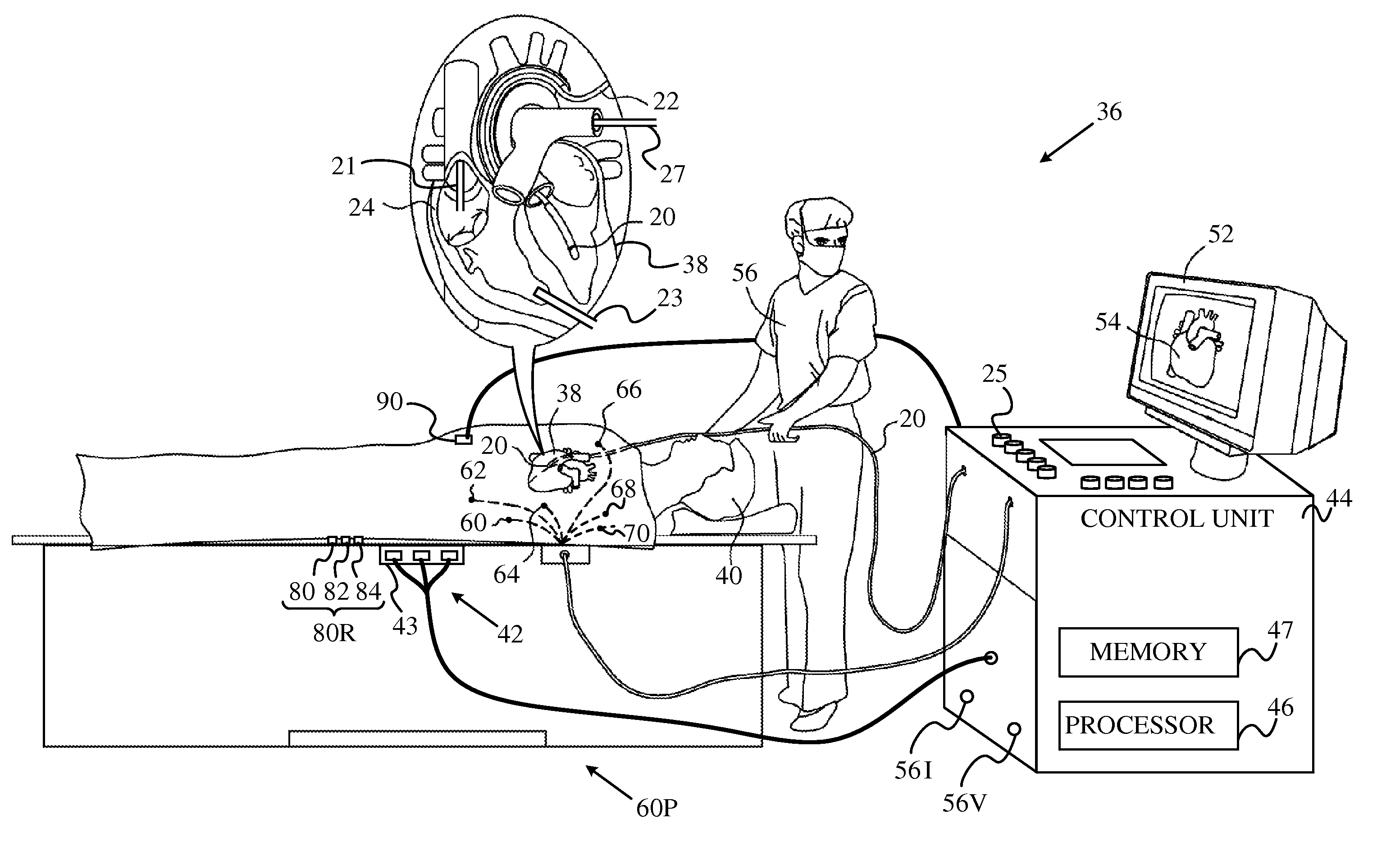
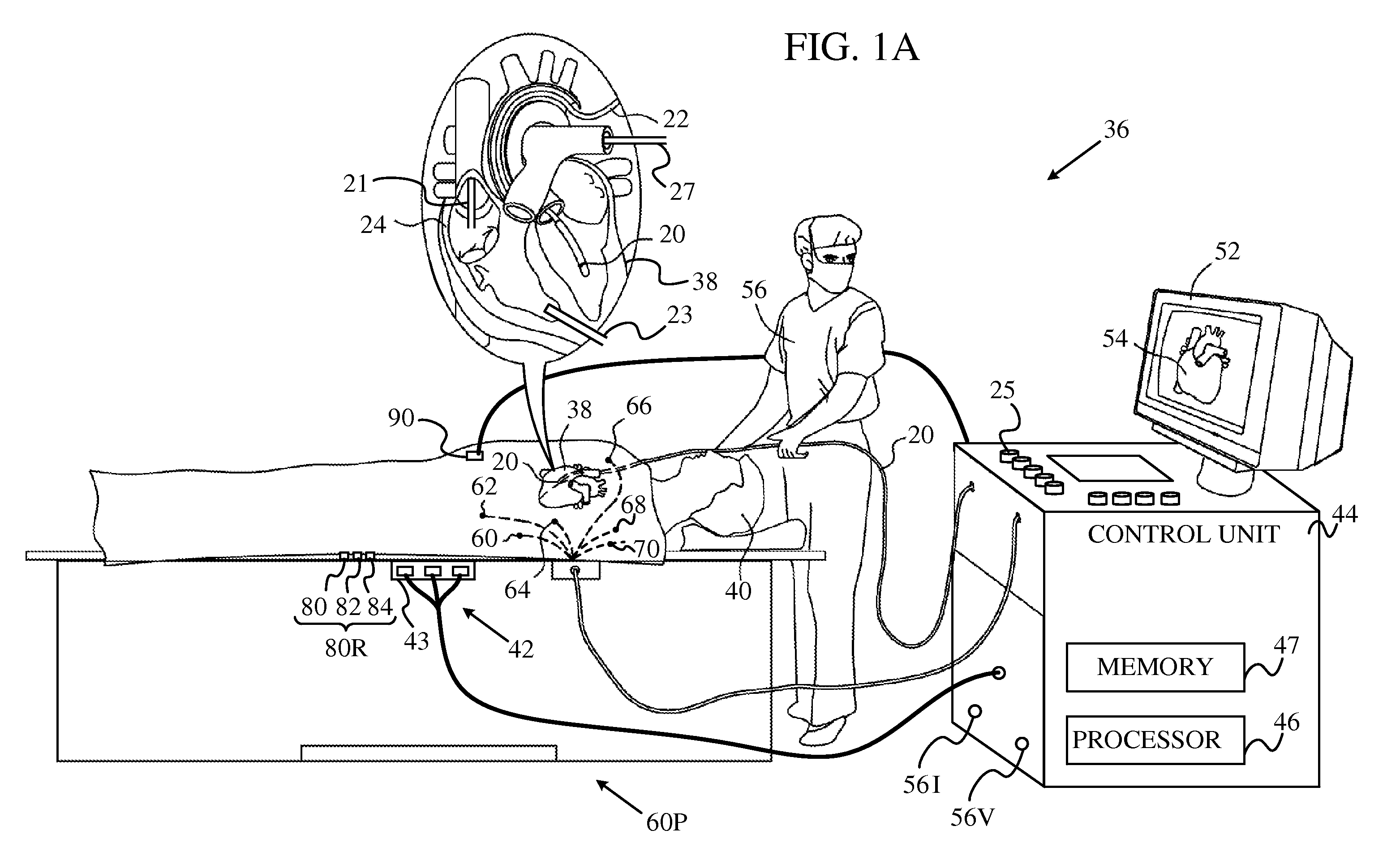
[0033]An embodiment of the present invention provides a method for determining the location of a probe within the body of a patient, typically a subject undergoing a medical procedure. The method compensates for errors in the measured location that are caused by respiration of the patient.

[0034]In order to compensate for the respiration, a probe is located in the body of the patient, and body-electrodes are positioned in galvanic contact with the patient's body. A processor tracks positions of the probe during respiration of the patient. In addition, the processor measures currents between an electrode of the probe and the body-electrodes. From the currents the processor derives indications of impedances between the body-electrodes, as respiration indicators, during the respiration. The processor generates an optimal correlation of a parameterized function of the indicators with the probe positions. The parameterized function may be expressed as a matrix correlating the posi...


PUM


Abstract

A method, including positioning body-electrodes in galvanic contact with a body of a patient and locating a probe in the body of the patient. The method further includes tracking positions of the probe during respiration of the patient and determining indications related to impedances between the body-electrodes during the respiration. The method also includes calculating a function relating the positions of the probe to the indications, and applying the function to identify end-expirium points of the respiration based on subsequent indications related to the impedances.

Description

FIELD OF THE INVENTION[0001]The present invention relates generally to sensing the position of an object placed within a living body, and specifically to detection and compensation for respiration effects.BACKGROUND OF THE INVENTION[0002]A wide range of medical procedures involve placing objects, such as sensors, tubes, catheters, dispensing devices, and implants, within the body. Real-time imaging methods are often used to assist doctors in visualizing the object and its surroundings during these procedures. In most situations, however, real-time three-dimensional imaging is not possible or desirable. Instead, systems for obtaining real-time spatial coordinates of the internal object are often utilized. In these systems compensation for effects of respiration may be required.[0003]U.S. Patent Application 2009 / 0030307, to Govari et al., whose disclosure is incorporated herein by reference, describes a method for position tracking that includes placing an internal reference probe in ...

Claims


Application Information

Patent Timeline
Patent Type & Authority Applications(United States)
IPC IPC(8): A61B5/05
CPCA61B19/5244A61B2017/00699A61B2019/5253A61B2019/5251A61B2019/5246A61B2034/2046A61B2034/2053A61B34/20A61B2034/2051A61B5/0809A61B5/062A61B5/063A61B5/7282
Inventor BAR-TAL, MEIR
Owner BIOSENSE WEBSTER (ISRAEL) LTD
Why Eureka
Try Eureka