
Heat pipe with a radial flow shunt design

a radial flow and heat pipe technology, applied in the field of heat pipes, can solve the problems of heat source not being able to efficiently transfer heat subject to phase change, and the structure of regular composite wicks is not designed for multi-heat-source applications, so as to enhance the working fluid flow speed and phase cycling, and avoid dry burning

Inactive Publication Date: 2012-07-12
HORNG CHIN HSING
View PDF5 Cites 15 Cited by
  • Summary
  • Abstract
  • Description
  • Claims
  • Application Information

AI Technical Summary

Benefits of technology

[0006]The present invention has been accomplished under the circumstances in view. It is the main object of the present invention to provide a heat sink, which has a second wick structure sintered at a first wick structure to increase the working fluid storage capacity and to enhance the working fluid flowing speed and phase cycling, avoiding dry burning and improving the fluid evaporation speed.

Problems solved by technology

However, regular composite wick structures are not designed for multi-heat-source application.
However, because the channels extend axially in a parallel manner, the working fluid cannot flow from one channel to another.
Thus, the working fluid in the channels opposite to the heat source or at each lateral side relative to the heat source cannot efficiently transfer heat subject to phase change.

Method used


Image

  • Heat pipe with a radial flow shunt design
  • Heat pipe with a radial flow shunt design
  • Heat pipe with a radial flow shunt design

Examples


Embodiment Construction

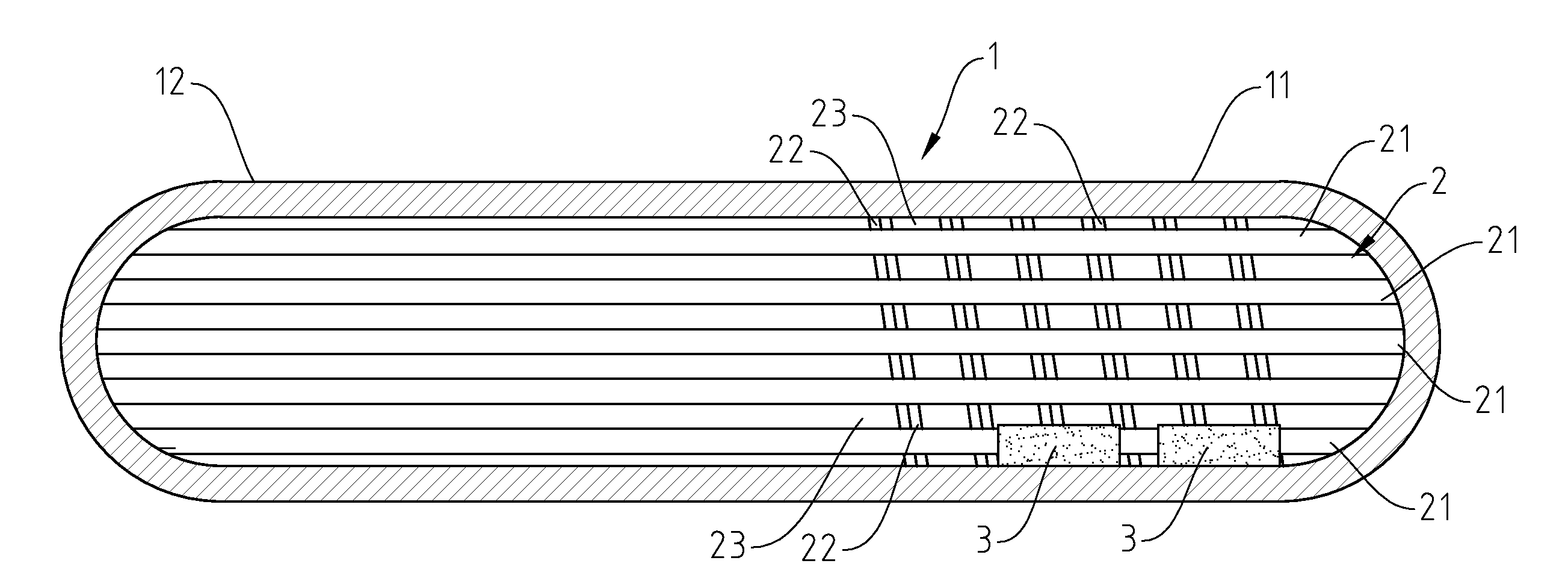
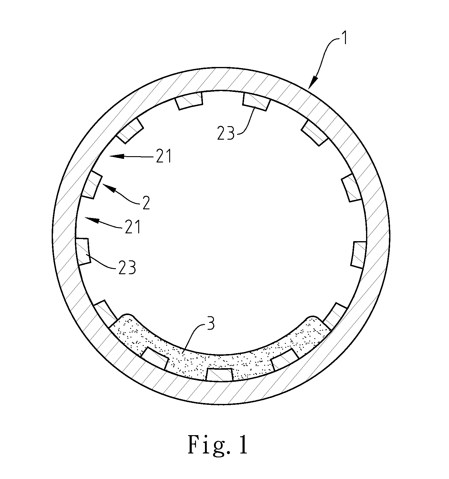
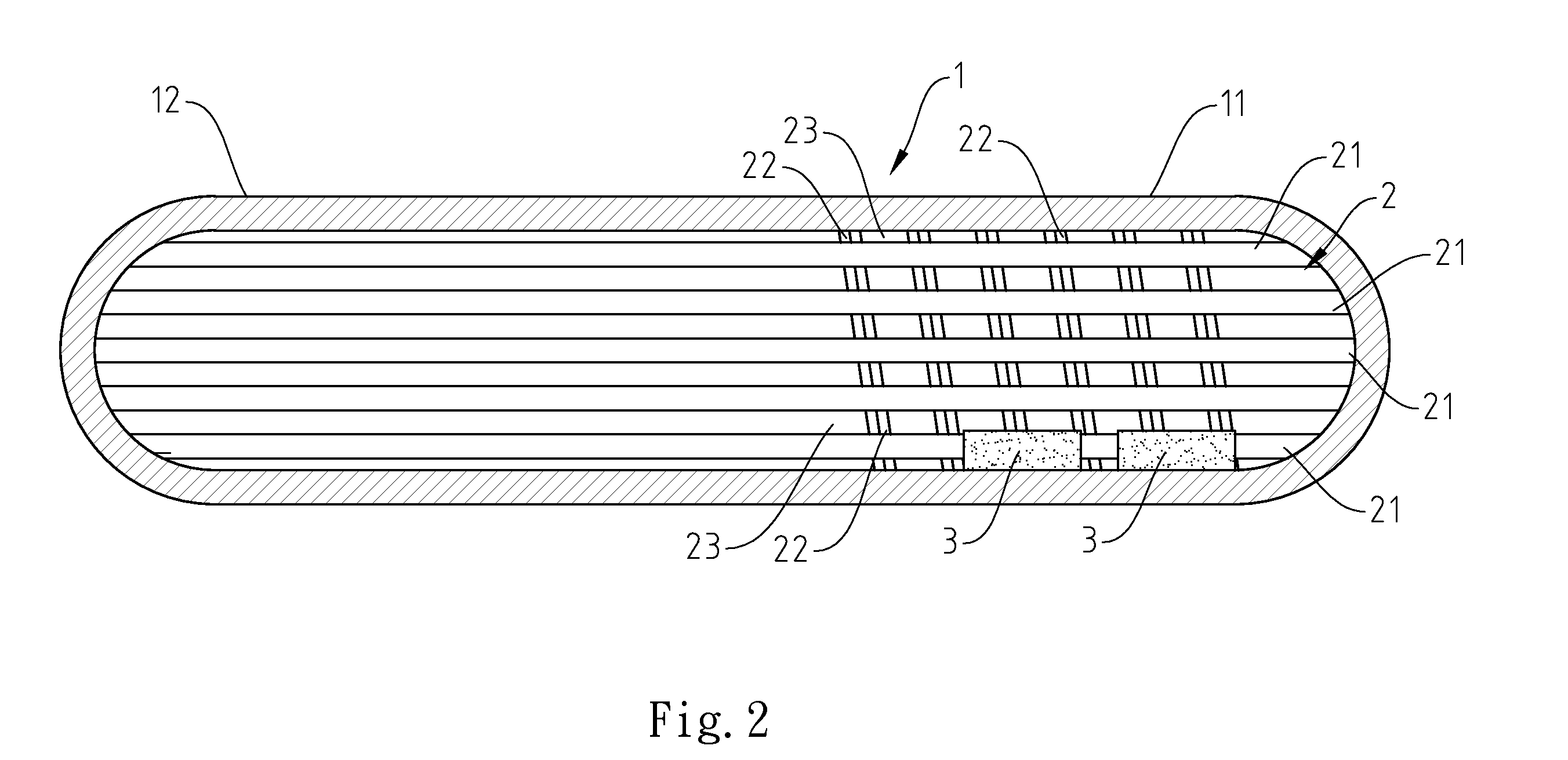
[0014]Referring to FIGS. 1 and 2, a heat pipe in accordance with a first embodiment of the present invention is shown comprising a pipe body 1, a first wick structure 2 located on the surface of the inside wall of the pipe body 1, and a second wick structure 3 formed on a part of the surface of the first wick structure 2 by a sintering technique.

[0015]The pipe body 1 comprises opposing evaporation segment 11 and condensing segment 12, and has a working fluid filled therein.

[0016]The first wick structure 2 comprises a plurality of ribs 23 axially extending through the evaporation segment 11 and the condensing segment 12, a channel 21 defined between each two adjacent ribs 23, and a plurality of spiral grooves 22 arranged in the evaporation segment 11 and transversely cut through the ribs 23 to keep the channels 21 in communication with one another. Thus, the channels 21 are intersected with the spiral grooves 22, forming a lattice pattern. The spiral grooves 22 can be formed by means...


PUM


Abstract

A heat pipe includes a pipe body filled up with a working fluid and having opposing evaporation segment and condensing segment, a first wick structure having ribs axially extending through the evaporation segment and the condensing segment, a channel defined between each two adjacent ribs and grooves transversely cut through the ribs, and a second wick structure sintered and joined to a predetermined part of the first wick structure in the evaporation segment to fill in the channels and the spiral grooves and to cover the ribs.

Description

BACKGROUND OF THE INVENTION[0001]1. Field of the Invention[0002]The present invention relates to heat pipes for transfer of heat between two solid interfaces and more particularly, to a heat pipe with a composite wick structure having a radial shunt design.[0003]2. Description of the Related Art[0004]For the advantages of small size, light weight, long lifespan, high thermal conductivity, long distance heat transfer and pressure-free heat transfer, heat pipe is intensively used in different fields for heat transfer and dissipation. A heat pipe combines the principles of both thermal conductivity and phase transition to efficiently manage the transfer of heat between two a hot side and a cold side. At the hot side of the heat pipe, a liquid in contact turns into a vapor by absorbing the heat of the surface of the hot side. The vapor condenses back into a liquid at the cold side, releasing the latent heat. The liquid then returns to the hot side through the wick structure where it eva...

Claims


Application Information

Patent Timeline
Patent Type & Authority Applications(United States)
IPC IPC(8): F28D15/04
CPCF28D15/02F28F1/40F28D15/046
Inventor HORNG, CHIN-HSING
Owner HORNG CHIN HSING
Learn More